SCRN251R-F Cornell Dubilier Electronics (CDE), SCRN251R-F Datasheet - Page 3
SCRN251R-F
Manufacturer Part Number
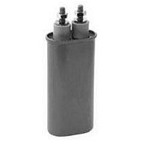
SCRN251R-F
Description
CAP FILM 3.0UF 2KV BOLT
Manufacturer
Cornell Dubilier Electronics (CDE)
Series
SCRr
Datasheet
1.SCRN220R-F.pdf
(3 pages)
Specifications of SCRN251R-F
Capacitance
3.0µF
Voltage - Ac
2000Vpk (2kV)
Dielectric Material
Paper, Metallized
Tolerance
±10%
Operating Temperature
-40°C ~ 65°C
Mounting Type
Chassis Mount
Package / Case
Radial, Can - Screw Terminals
Size / Dimension
2.910" L x 1.910" W (73.91mm x 48.51mm)
Height
4.750" (120.65mm)
Termination
Screw Terminals
Lead Spacing
1.380" (35.05mm)
Features
High Frequency and High Stability
Capacitor Dielectric Type
Paper
Capacitance Tolerance
± 10%
Voltage Rating
2000VDC
Termination Type
Radial Threaded
Working Voltage, Dc
2000V
Lead Free Status / RoHS Status
Lead free / RoHS Compliant
Esr (equivalent Series Resistance)
-
Voltage - Dc
-
Lead Free Status / RoHS Status
Lead free / RoHS Compliant, Lead free / RoHS Compliant


How to Choose a Commutating Capacitor
1. From circuit analysis or measurement, determine
application values for these six parameters:
2. Choose a capacitor from the ratings table of the desired
nominal capacitance with a peak voltage rating no less than
your maximum peak voltage.
3. Check that your application’s rms current is no more
than the capacitor’s Max. Amps RMS. You can calculate
Using Volt-Ampere Ratings
T
of the sine wave voltage and current that may be applied at
65 ºC without overheating the capacitor and reducing its
expected life. For other temperatures and pulsed current, use
the multipliers of Figures 2 and 3 to derate the Max VA rating.
The Max Amps RMS rating is set by the capability of the
capacitor terminals. Exceeding this limit can damage the
terminals and cause capacitor failure.
Calculate the capacitor’s actual VA load as the product of the
rms voltage across the capacitor and the rms current through
the capacitor. To calculate rms current for an applied sine
wave or squarewave voltage, use these equations.
For a sinewave voltage the current is:
and for a squarewave the current is:
where (f) is repetition frequency in Hz, C is nominal
capacitance in µF, ∆V the peak-to-peak squarewave amplitude
in volts, (t) is the pulse width in µs and T is the pulse period
in µs.
T
he capacitors maximum VA rating is the maximum product
he peak current for the square wave voltage is:
CDE Cornell Dubilier • 1605 E. Rodney French Blvd. • New Bedford, MA 02744 • Phone: (508)996-8561 • Fax: (508)996-3830 • www.cde.com
Nominal capacitance in µF
Current pulse width in µs
Current pulse period in µs
Maximum peak voltage
Continuous AC voltage in Vrms
Maximum volt-amps (VA)
Irms = C∆V/[0.64(tT)
Irms = 2π fCVrmsX10
Ipeak = C∆V/0.64t
0.5
] = Ipeak(t/T)
COPY & PASTE A CDE PART NUMBER TO CHECK STOCK ONLINE:
-6
0.5
Type SCR
the
following
4. Check that your application’s volt-amperes is not more
than the capacitor’s VA capability. The VA capability is the
max VA rating times the Volt-Ampere multiplier from Figure
2 (Current Pulse Width) and that times the Volt-Ampere
Multiplier from Figure 3 (Ambient Temperature). See the
following section for more on using volt-ampere multipliers
.
If you need a greater VA capability, repeat these steps for a
higher peak voltage capacitor or consider connecting units in
parallel to divide the VA required. For up to peak voltage of
600 V, you may also consider polypropylene film dielectric
units, Catalog Numbers SCRN262R through SCRN266R,
with higher VA capability.
current from your Vrms using the equations in the
section.
Polypropylene
Commutating Capacitors
PP Film/Paper
Pulse Wave Applications
ΔV
V peak
I peak
Paper
Voltage
Current
Figure 1
Figure 2
Figure 3
GO
Related parts for SCRN251R-F
Image
Part Number
Description
Manufacturer
Datasheet
Request
R

Part Number:
Description:
CDE, 105°C 3 PIN LARGE RADIAL INVERTER GRADE LYTIC
Manufacturer:
Cornell Dubilier Electronics (CDE)
Part Number:
Description:
CDE, 105°C Ultra-High Ripple Motor Control Grade, Aluminun
Manufacturer:
Cornell Dubilier Electronics (CDE)
Part Number:
Description:
CDE,-55 C TO 105 C LONG LIFE, SWITCHING POWER GRADE RADIAL NC/NR
Manufacturer:
Cornell Dubilier Electronics (CDE)

Part Number:
Description:
Mica Capacitors DISC CDE 3/00 MICA 8200PF 1KV J
Manufacturer:
Cornell Dubilier Electronics (CDE)
Datasheet:

Part Number:
Description:
CAP 2200PF 50V FILM 5% 0805
Manufacturer:
Cornell Dubilier Electronics (CDE)
Datasheet:

Part Number:
Description:
CAP 1.0UF 100V FILM 10% 3925
Manufacturer:
Cornell Dubilier Electronics (CDE)
Datasheet:

Part Number:
Description:
CAP ALUM 16UF 450V AXIAL
Manufacturer:
Cornell Dubilier Electronics (CDE)
Datasheet:
Part Number:
Description:
CAP ALUM 160UF 250V AXIAL
Manufacturer:
Cornell Dubilier Electronics (CDE)
Datasheet:
Part Number:
Description:
CAP 6200UF 300V ELECT SCREW TERM
Manufacturer:
Cornell Dubilier Electronics (CDE)
Datasheet:

Part Number:
Description:
Multilayer Ceramic Capacitors (MLCC) - Leaded MONO CAP 50V .33uF
Manufacturer:
Cornell Dubilier Electronics (CDE)
Datasheet:

Part Number:
Description:
CAP PP FILM 1µF, 1.2KV, AXIAL
Manufacturer:
Cornell Dubilier Electronics (CDE)
Datasheet:
Part Number:
Description:
SMT-POL/AL(SPA
Manufacturer:
Cornell Dubilier Electronics (CDE)
Datasheet:

Part Number:
Description:
Encoders 8 OHM T-PAD WW ATTEN
Manufacturer:
Cornell Dubilier Electronics (CDE)
Datasheet:

Part Number:
Description:
CAPACITOR CERAMIC, 0.1UF, 50V, X7R, 1206
Manufacturer:
Cornell Dubilier Electronics (CDE)
Datasheet: