R82DC3100DQ50J Kemet, R82DC3100DQ50J Datasheet - Page 3
R82DC3100DQ50J
Manufacturer Part Number
R82DC3100DQ50J
Description
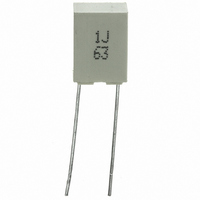
CAP FLM .1UF 63V POLY MKT RAD
Manufacturer
Kemet
Series
MKT Arcotronicsr
Specifications of R82DC3100DQ50J
Capacitance
0.1µF
Voltage - Dc
63V
Dielectric Material
Polyester, Metallized
Tolerance
±5%
Operating Temperature
-55°C ~ 105°C
Mounting Type
Through Hole
Package / Case
Radial
Size / Dimension
0.283" L x 0.098" W (7.20mm x 2.50mm)
Height
0.256" (6.50mm)
Termination
PC Pins
Lead Spacing
0.197" (5.00mm)
Features
General Purpose
Voltage Rating
63 Volts
Termination Style
Radial
Dimensions
2.5 mm W x 7.2 mm L x 6.5 mm H
Operating Temperature Range
- 55 C to + 105 C
Product
Metallized Polyester Film Capacitors
Lead Free Status / RoHS Status
Lead free / RoHS Compliant
Esr (equivalent Series Resistance)
-
Voltage - Ac
-
Lead Free Status / Rohs Status
Lead free / RoHS Compliant
Other names
399-5444-3


eleCtriCal CharaCteriStiCS
rated voltage (V
rated temperature (t
temperature derated voltage:
for temperatures between +85°C and +105°C a decreasing
factorof1.25%perdegree°ContheratedvoltageV
anda.c.)hastobeapplied.
Capacitance range:
Capacitance values:
Capacitance tolerances (measured at 1 khz):
±5% (J); ±10% (K); ±20% (M).
total self-inductance (l): ≈7nH
max1nHper1mmleadandcapacitorlength.
Dissipation factor (Df):
tgδ 10
insulation resistance:
test voltage between terminations:
1.4xV
05/2007
10
100
kHz
test conditions
Temperature:
Voltage charge time:
Voltage charge:
Performance
for V
≥ 15000 MΩ for C ≤ 0.33µF
≥ 5000 s
≥ 1000 s
for V
≥ 30000 MΩ
*Typicalvalue
1
R
-4
applied for 2 s at +25°C±5°C.
at +25°C ±5°C
C
r
r
≤
≤
≤
≤100 Vdc
>100Vdc
≤
80
120
250
0.1µF
for C > 0.33µF and ≤1µF
for C > 1µF
r
):
C>0.1µF
≤
≤
r
80
120
):
100Vdc forV
50Vdc forV
250Vdc 400Vdc
+85 °C
1000pFto4.7µF
E6series(IEC60063Norm).
+25°C±5°C
1 min
50Vdc
63Vdc 100Vdc
R
R
<100Vdc
≥100 Vdc
R
(d.c.
0
metalliZeD PolyeSter film CaPaCitor
D.C. mUltiPUrPoSe aPPliCationS
p = 5 mm
PRODUCT CODE: r82
teSt methoD anD PerformanCe
Damp heat, steady state:
endurance:
resistance to soldering heat:
long term stability (after two years):
reliaBility:
ReferenceMILHDB217
test conditions
Temperature:
Relative humidity (RH):
Test duration:
Performance
Capacitance change |∆C/C|: ≤ 5%
DF change (∆tgδ):
Insulation resistance:
test conditions
Temperature:
Test duration:
Voltage applied:
Performance
Capacitance change |∆C/C|: ≤ 5%
DF change (∆tgδ): ≤ 30x10
Insulation resistance:
test conditions
Solder bath temperature:
Dipping time (with heat screen):10 s ±1 s
Performance
Capacitance change |∆C/C|: ≤2%
DF change (∆tgδ):
Insulation resistance:
Storage: standardenvironmentalconditions(seepage12).
Performance
Capacitance change |∆C/C|: ≤ 3% for C≤ 0.1µF
application conditions:
Temperature:
Voltage:
Failure rate:
(1FIT=1x10
failure criteria:
(accordingtoDIN44122)
Shortoropencircuit
Capacitance change |∆C/C|: > 10%
DF change (∆tgδ):
Insulation resistance:
-9
failures/componentsxh)
≤ 20x10
≤ 30x10
≤ 20x10
-4
-4
≤ 2% for C> 0.1µF
+40°C±2°C
93% ±2%
56 days
≤ 50x10
≥ 50% of initial limit.
+105°C ±2°C
2000 h
1.25xV
at
≥50% of initial limit.
+260°C±5°C
≥ initial limit.
+40°C±2°C
0.5xV
≤ 1 FIT
> 2 x initial limit.
< 0.005 x initial limit.
-4
-4
at 10kHz for C≤1µF
at 10kHz for C≤ 1µF
at
1kHz
R
1kHz forC>1µF
C
-4
at1kHz
forC>1µF
MKTSeries
r82
Related parts for R82DC3100DQ50J
Image
Part Number
Description
Manufacturer
Datasheet
Request
R

Part Number:
Description:
CAP, KEMET #F601BL105K250C
Manufacturer:
Kemet
Datasheet:
Part Number:
Description:
Manufacturer:
Kemet
Datasheet:
Part Number:
Description:
Manufacturer:
Kemet
Datasheet: