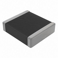
LDEID3100KA0N00 Kemet, LDEID3100KA0N00 Datasheet - Page 9

LDEID3100KA0N00
Manufacturer Part Number
LDEID3100KA0N00
Description
CAP FILM .1UF 250V SMD
Manufacturer
Kemet
Series
LDE Arcotronicsr
Specifications of LDEID3100KA0N00
Capacitance
0.1µF
Voltage - Ac
120V
Voltage - Dc
250V
Dielectric Material
Polyethylene (PEN)
Tolerance
±10%
Operating Temperature
-55°C ~ 125°C
Mounting Type
Surface Mount
Package / Case
2220 (5750 Metric)
Size / Dimension
0.236" L x 0.197" W (6.00mm x 5.00mm)
Height
0.161" (4.10mm)
Termination
Solder Pads
Features
General Purpose
Voltage Rating
250 Volts
Dissipation Factor Df
0.8
Operating Temperature Range
- 55 C to + 125 C
Dimensions
5.1 mm W x 5.7 mm L x 4.1 mm H
Product
PEN SMD Film Capacitors
Termination Style
SMD/SMT
Lead Free Status / RoHS Status
Lead free / RoHS Compliant
Lead Spacing
-
Esr (equivalent Series Resistance)
-
Lead Free Status / Rohs Status
Lead free / RoHS Compliant
Other names
399-5481-2
LDE
Electrical data
Tests and performances
Plates
Winding
Terminations
Marking
Climatic category
Operating temperature
range
Rated voltage (V
Category voltage (V
Size range
Capacitance range
Capacitance values
Capacitance
tolerances
Dissipation factor (tgδ)
Dielectric absorption
Insulation resistance
Surge voltage test
Maximum dv / dt
Damp heat
(40°C/93% R.H.; 56 days)
Endurance
(125 °C; 2000 h; 1.25 x V
Rapid change of
temperature
(1h at -55 °C;1h at
+125 °C; 1000 cycles)
Reflow
(as per reflow
recommendations, see
page 14)
Bending
(1 to 6 mm deflection)
Long term stability
(2 years)
Reliability
(REF MIL HDBK 217)
series - PEN dieletric RoHS 6 - technical data
R
)
C
C
)
)
Aluminium layer deposited by evaporation under vacuum.
Non inductive - Stacked technology.
Four layers: aluminium, brass, nickel, pure tin.
On packaging only.
55 / 125 / 56
-55 to +125 °C
50 - 63 - 100 - 250 - 400 - 630 - 1000 V
V
between 105 and 125 °C a decreasing
factor of 1.25% per degree °C has to be
applied on the rated voltage (D.C. and
A.C.)
12.06 to 60.54
(customized sizes available upon request)
1000 pF to 4.7 μF
E12 series
Standard: K = ± 10 %
(J = ±5% available upon request and
review of project/application)
≤ 0.8 % (T = 25 ± 5 °C; f = 1 kHz)
0.8%
≥ 1 GΩ for C ≤ 0.33 μF
≥ 400 s for C > 0.33 μF
Test conditions:
T = 25 ± 5 °C; charging time: 1 min.
Charging voltage:
10 V
100 V
1.4 x V
for V
1.5 x V
for V
100 V / μs for V
300 V / μs for V
│∆C/C│≤ 7%;│∆tgδ│≤ 50 x 10
IR ≥ 50% of the limit value
│∆C/C│≤ 5%;│∆tgδ│≤ 50 x 10
IR ≥ 50% of the limit value
│∆C/C│≤ 5%
│∆tgδ│≤ 50 x 10
IR ≥ limit value
No mechanical damage
│∆C/C│≤ 3%
│∆tgδ│≤ 50 x 10
IR ≥ limit value
No mechanical damage
│∆C/C│≤ 1%
No visible damage on the terminations
(pealing) neither on the body (cracking)
│∆C/C│≤ 3% for sizes ≤ 22.20
│∆C/C│≤ 2% for sizes > 22.20
Failure rate ≤ 1 Fit
1 Fit = 10
C
= V
DC
R
R
DC
≤ 630 V
= 1000 V
R
R
R
for V
up to 105 °C. For temperatures
for V
(2 s; T = 25 ± 5 °C)
(2 s; T = 25 ± 5 °C)
-9
failures / (components * hours)
R
R
< 100 V
DC
≥ 100 V
DC
R
R
-4
-4
≤ 630 V
= 1000 V
DC
DC
M = ± 20 %;
DC
DC
-4
-4
;
;
DC
9
When a capacitor is used in A.C. applications at high frequency,
the consequent internal heating may cause the risk of smoke or
fire. This is due to the high current flowing through the capacitor’s
Equivalent Series Resistance.
The formula to calculate the maximum power [W] dissipated by the
capacitor is the following:
(N: number of significant harmonics)
The formula to calculate the maximum power [W] that can be
dissipated by the capacitor is the following:
It must be: Pc
Please refer to the table and graph below for ∆T
(T
hottest contact point - i.e. tracks - whichever is higher, in the worst
operating conditions in °C)
[°C/W]
[°C/W]
H
[mm]
H
[mm]
Size
Size
R
R th
max
max
h
th
: maximum ambient temperature surrounding the capacitor or
12.06
175
1.2
3.6
93
Pc
=
∑
i=
12.10
N
40.30
max
165
2.1
4.5
max
88
1
2
I
�
=
≤ Pc
rms
2
157 151
1.7 2.6
f
i
18.12
∑
i=
5.5
N
*
84
_
1
lim
C
i
V
Dissipation (A.C. applications)
rms
*
2
tg
135
2.3
3.6
75
SMD Film Capacitors
_
δ
i
max
2 *
22.20
50.40
128
�
3.3
4.5
70
(f
f
i
i
*
)
C
122
4.4
5.7
66
*
tg
lim
δ
114
and R
3.5
3.6
max
58
(f
th
28.24
60.54
i
108
4.5
4.5
55
)
values
=
07/2008
103
5.4
5.7
52


