MPDTY301S Murata Electronics North America, MPDTY301S Datasheet - Page 18
MPDTY301S
Manufacturer Part Number
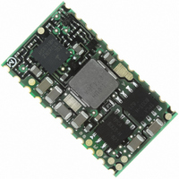
MPDTY301S
Description
CONV DC/DC 23.1W .8-3.3VOUT SMT
Manufacturer
Murata Electronics North America
Series
MPDr
Type
Point of Load (POL) Non-Isolated with UVLOr
Datasheet
1.MPDTY301S.pdf
(20 pages)
Specifications of MPDTY301S
Output
0.8 ~ 3.3V
Number Of Outputs
1
Power (watts)
23W
Mounting Type
Surface Mount
Voltage - Input
4.5 ~ 5.5V
Package / Case
22-DIP SMD Module
1st Output
0.8 ~ 3.3 VDC @ 7A
Size / Dimension
1.09" L x 0.61" W x 0.17" H (27.8mm x 15.4mm x 4.2mm)
Power (watts) - Rated
23.1W
Operating Temperature
-40°C ~ 85°C
Efficiency
94%
Lead Free Status / RoHS Status
Lead free / RoHS Compliant
3rd Output
-
2nd Output
-
Other names
490-4572
490-4572-1
490-4572-1
490-4572-1
490-4572-1


2010.12.29
14. Notice
1. This datasheet is downloaded from the website of Murata Manufacturing co., ltd. Therefore, it’ s specifications are subject to change or our
2. This datasheet has only typical specifications because there is no space for detailed specifications. Therefore, please approve our product
14. 1. Input / output capacitor
14. 2. Wiring of input / output capacitor
14. 3. This product could not be operated parallel or series.
14. 4. Please do not use a connector or a socket for connection with your board of this product.
14. 5. Be sure to provide an appropriate fail-safe function on your product to prevent a second damage that
14. 6. Please connect the input terminal with proper polarity. If you connect wrong polarity, the DC-DC
products in it may be discontinued without advance notice. Please check with our sales representatives or product engineers before ordering.
specifications or transact the approval sheet for product specifications before ordering.
Note:
①Please be sure to check normal operation on your system.
②Please use low impedance capacitors with good high frequency characteristic.
③Please shorten those leads of each capacitor as much as possible, and make sure the lead inductance low.
④Both input-side and output side, please make the wiring loop between plus and minus as small as possible.
⑤Please design the print pattern of the main circuit as wide and short as possible.
When an inductance or a switch devise is connected to the input line, or when you use a power supply
with output inductance as the input voltage source, the input voltage of the DC-DC Converter will be
fluctuated.
By this input voltage fluctuation, the transient load response of the DC-DC converter may be deteriorated
or abnormal oscillation may occur. So please confirm normal operation on each application.
Please use external input capacitor in order to decrease inductance of input line.
In case you use external output capacitor in order to improve transient load response, please use input
capacitor to prevent abnormal oscillation. When you use external capacitors, following capacitors are
recommendable.
Input capacitor C1 : Please use capacitors more than 100μF of low impedance in high frequency range.
Output capacitor C2 : Please use capacitors less than 1000μF
In the case of input / output capacitor connection, in order to reduce electrical noise , please design
PCBs with consideration of the following item.
The influence of leakage inductance can be reduced.
Electrical performance may be deteriorated the influence of contact resistance.
Please be sure to mount this product with solder.
may be caused by the abnormal function or the failure of our product.
Converter may be broken. In the case of the DC-DC Converter is damaged, abnormal input current may
flow in, and abnormal overheat of the DC-DC Converter, or some damage of your products may occur.
Please use a diode and a fuse to as following figure.
Make wiring roop small
+Vin
diode
+Vin
- Vin
shorten the leads and pattern
※Please select diode and fuse after confirming the operation.
fuse
C1
IN
+Vin
-
+
DC - DC
Converter
GND
+Vout
OUT
Make wiring roop small
shorten the leads and pattern
-
+
+
C2
+Vout
Load
MPDTY301S,MPDTY302S DATA Sheet
Load
2010.12.29
18
Related parts for MPDTY301S
Image
Part Number
Description
Manufacturer
Datasheet
Request
R

Part Number:
Description:
CONV DC/DC 3A 3-5.5VIN 95% EFF
Manufacturer:
Murata Electronics North America
Datasheet:

Part Number:
Description:
CONV DC/DC 10W .8-5VOUT 2A SMT
Manufacturer:
Murata Electronics North America
Datasheet:

Part Number:
Description:
CONV DC/DC 33W 1.2-5.5VOUT 6A
Manufacturer:
Murata Electronics North America
Datasheet:

Part Number:
Description:
CONV DC/DC 44W .8-5.5VOUT SMT
Manufacturer:
Murata Electronics North America

Part Number:
Description:
CONV DC/DC 17.5W .8-2.5VOUT SMT
Manufacturer:
Murata Electronics North America
Datasheet:

Part Number:
Description:
CONV DC/DC 52.8W .8-3.3VOUT SMT
Manufacturer:
Murata Electronics North America

Part Number:
Description:
CONV DC/DC 9W 1.5VOUT 6A SMT
Manufacturer:
Murata Electronics North America
Datasheet:

Part Number:
Description:
CONV DC/DC 7.2W 1.2VOUT 6A SMT
Manufacturer:
Murata Electronics North America
Datasheet:

Part Number:
Description:
CONV DC/DC 40W .8-2.5VOUT SMT
Manufacturer:
Murata Electronics North America

Part Number:
Description:
CONV DC/DC 19.8W 3.3VOUT 6A SMT
Manufacturer:
Murata Electronics North America
Datasheet:

Part Number:
Description:
BUZZER PIEZO 25VP-P SMD
Manufacturer:
Murata Electronics North America

Part Number:
Description:
CAP 4-ARRAY 680PF 100V X7R 1206
Manufacturer:
Murata Electronics North America
Datasheet:
Part Number:
Description:
CAP 4-ARRAY 1000PF 100V X7R 1206
Manufacturer:
Murata Electronics North America
Datasheet:
Part Number:
Description:
CAP 4-ARRAY 1800PF 100V X7R 1206
Manufacturer:
Murata Electronics North America
Datasheet:
Part Number:
Description:
CAP 4-ARRAY 68000PF 16V X7R 1206
Manufacturer:
Murata Electronics North America
Datasheet: