LTM4618IV#PBF Linear Technology, LTM4618IV#PBF Datasheet - Page 13
LTM4618IV#PBF
Manufacturer Part Number
LTM4618IV#PBF
Description
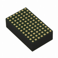
IC DC-DC UMODULE BUCK 6A 84-LGA
Manufacturer
Linear Technology
Series
µModuler
Type
Point of Load (POL) Non-Isolatedr
Datasheet
1.LTM4618EVPBF.pdf
(24 pages)
Specifications of LTM4618IV#PBF
Output
0.8 ~ 5 V
Number Of Outputs
1
Power (watts)
30W
Mounting Type
Surface Mount
Voltage - Input
4.5 ~ 26.5 V
Package / Case
84-LGA
1st Output
0.8 ~ 5 VDC @ 6A
Size / Dimension
0.59" L x 0.35" W x 0.17" H (15mm x 9mm x 4.32mm)
Power (watts) - Rated
30W
Operating Temperature
-40°C ~ 125°C
Lead Free Status / RoHS Status
Lead free / RoHS Compliant
3rd Output
-
2nd Output
-
Available stocks
Company
Part Number
Manufacturer
Quantity
Price


Slope Compensation
The module has already been internally compensated for
all output voltages. LTpowerCAD is available for further
control loop optimization.
RUN Pin
The RUN pin has a 1μA pull-up current source that will
enable the device in a fl oat condition. A voltage divider
can be used to enable a UVLO function using the RUN
pin. See Figure 21.
Fault Conditions: Current Limit and Overcurrent
Foldback
The LTM4618 has a current mode controller, which inher-
ently limits the cycle-by-cycle inductor current not only in
steady-state operation, but also in transient.
To further limit current in the event of an overload condi-
tion, the LTM4618 provides foldback current limiting. If the
output voltage falls by more than 40%, then the maximum
output current is progressively lowered to about 25% of
its full current limit value.
Thermal Considerations and Output Current Derating
The thermal resistances reported in the Pin Confi guration
section of the data sheet are consistent with those param-
eters defi ned by JESD51-9 and are intended for use with
fi nite element analysis (FEA) software modeling tools that
leverage the outcome of thermal modeling, simulation,
and correlation to hardware evaluation performed on a
μModule regulator package mounted to a hardware test
board—also defi ned by JESD51-9 (“Test Boards for Area
Array Surface Mount Package Thermal Measurements”).
The motivation for providing these thermal coeffi cients in
found in JESD 51-12 (“Guidelines for Reporting and Using
Electronic Package Thermal Information”).
Many designers may opt to use laboratory equipment
and a test vehicle such as the demo board to anticipate
the μModule regulator’s thermal performance in their ap-
plication at various electrical and environmental operating
conditions to compliment any FEA activities. Without FEA
software, the thermal resistances reported in the Pin Con-
fi guration section are in-and-of themselves not relevant to
APPLICATIONS INFORMATION
providing guidance of thermal performance; instead, the
derating curves provided in the data sheet can be used in
a manner that yields insight and guidance pertaining to
one’s application-usage, and can be adapted to correlate
thermal performance to one’s own application.
The Pin Confi guration section shows four thermal coef-
fi cients explicitly defi ned in JESD 51-12; these coeffi cients
are quoted or paraphrased below:
• θ
• θ
• θ
• θ
ent, is the natural convection junction-to-ambient
air thermal resistance measured in a one cubic foot
sealed enclosure. This environment is sometimes
referred to as “still air” although natural convection
causes the air to move. This value is determined with
the part mounted to a JESD 51-9 defi ned test board,
which does not refl ect an actual application or viable
operating condition.
bottom of the product case, is the junction-to-board
thermal resistance with all of the component power
dissipation fl owing through the bottom of the pack-
age. In the typical μModule regulator, the bulk of the
heat fl ows out the bottom of the package, but there
is always heat fl ow out into the ambient environment.
As a result, this thermal resistance value may be use-
ful for comparing packages but the test conditions
don’t generally match the user’s application.
of the product case, is determined with nearly all of
the component power dissipation fl owing through
the top of the package. As the electrical connections
of the typical μModule regulator are on the bottom
of the package, it is rare for an application to operate
such that most of the heat fl ows from the junction to
the top of the part. As in the case of θ
value may be useful for comparing packages but the
test conditions don’t generally match the user’s ap-
plication.
printed circuit board, is the junction-to-board thermal
resistance where almost all of the heat fl ows through
the bottom of the μModule regulator and into the
JA
JCbottom
JCtop
JB
, the thermal resistance from junction to ambi-
, the thermal resistance from junction to the
, the thermal resistance from junction to top
, the thermal resistance from junction to the
LTM4618
JCbottom
, this
13
4618fa
Related parts for LTM4618IV#PBF
Image
Part Number
Description
Manufacturer
Datasheet
Request
R

Part Number:
Description:
6a Dc/dc
Manufacturer:
Linear Technology Corporation
Datasheet:

Part Number:
Description:
BOARD DEMO LTM4618
Manufacturer:
Linear Technology
Datasheet:
Part Number:
Description:
CD ROM LINEARVIEW DATASHEETS
Manufacturer:
Linear Technology
Part Number:
Description:
Standalone Linear Li-Ion Battery Charger with Thermal Regulation in ThinSOT
Manufacturer:
Linear Technology Corporation
Datasheet:
Part Number:
Description:
Low noise, high frequency, 8th order linear phase lowpass filter
Manufacturer:
Linear Technology Corporation
Datasheet:
Part Number:
Description:
Manufacturer:
Linear Technology Corporation
Datasheet:
Part Number:
Description:
Manufacturer:
Linear Technology Corporation
Datasheet:
Part Number:
Description:
Manufacturer:
Linear Technology Corporation
Datasheet:
Part Number:
Description:
Manufacturer:
Linear Technology Corporation
Datasheet:
Part Number:
Description:
Manufacturer:
Linear Technology Corporation
Datasheet:
Part Number:
Description:
Manufacturer:
Linear Technology Corporation
Datasheet:
Part Number:
Description:
Manufacturer:
Linear Technology Corporation
Datasheet:
Part Number:
Description:
Dual and Quad, JFET Input Precision High Speed Op Amps
Manufacturer:
Linear Technology Corporation
Datasheet:
Part Number:
Description:
Manufacturer:
Linear Technology Corporation
Datasheet:
Part Number:
Description:
1, 2, 6 and 8 Channel, 10-Bit Serial I/O Data Acquisition Systems
Manufacturer:
Linear Technology Corporation
Datasheet: