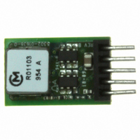
OKR-T/3-W12-C Murata Power Solutions Inc, OKR-T/3-W12-C Datasheet - Page 8

OKR-T/3-W12-C
Manufacturer Part Number
OKR-T/3-W12-C
Description
CONV DC/DC 15W 12VIN SIP
Manufacturer
Murata Power Solutions Inc
Series
Okami™ OKR-T/3r
Type
Point of Load (POL) Non-Isolatedr
Specifications of OKR-T/3-W12-C
Number Of Outputs
1
Output
0.59 ~ 6V
Power (watts)
15W
Mounting Type
Through Hole
Voltage - Input
4.5 ~ 14V
Package / Case
5-SIP Module
1st Output
0.59 ~ 6 VDC @ 3A
Size / Dimension
0.41" L x 0.30" W x 0.65" H (10.4mm x 7.6mm x 16.5mm)
Power (watts) - Rated
15W
Efficiency
93%
Approvals
cUL, EN, UL
Output Power
18 W
Input Voltage Range
4.5 V to 14 V
Input Voltage (nominal)
12 V
Output Voltage (channel 1)
0.591 V to 6 V
Output Current (channel 1)
3 A
Package / Case Size
SIP
Output Type
DC/DC Converter
Output Voltage
0.591 V to 6 V
Product
Non-Isolated / POL
Output Current
3A
Input Voltage
12V
Mounting Style
Through Hole
Pin Count
5
Lead Free Status / RoHS Status
Lead free / RoHS Compliant
Operating Temperature
-
3rd Output
-
2nd Output
-
Lead Free Status / Rohs Status
Lead free / RoHS Compliant
Other names
811-2115-5
The forced On/Off enable option for “E” models uses positive logic for the
external control. The converter may be powered ON by applying a positive volt-
age (logic HI) between the On/Off pin and the negative power input (-Vin). This
positive voltage is referred to –Vin and must be in the range of at least +2.0V
and not to exceed the power supply input voltage (+Vin). The current drain is 1
mA max. when turned on.
turn the converter OFF. The OFF condition may also be commanded by ground-
ing the pin or from an external logic LO voltage not to exceed +0.4 Volts. All
voltages are referred to the –Vin negative power input.
carefully compare your logic threshold voltages with that of the On/Off input.
www.murata-ps.com/support
If the On/Off pin is left open, an internal 100 Kilohm pulldown resistor will
If you wish to control the On/Off circuit by external logic rather than a switch,
100
90
85
80
75
70
95
OKR-T/3-W12-C PERFORMANCE DATA
0
0.5
Effi ciency vs. Line Voltage and Load Current @ 25°C
1
Max. Vgs for turn-off = 0.4V.
Min. Vgs for turn-on = 2.0V.
1.5
V
V
V
On/Off Control
IN
IN
IN
= 13.8V
= 12V
= 7V
2
Neg. Vin
Pos. Vin
2.5
Figure 6. On/Off Control Circuit for “E” Models
3
100
KΩ
3.5
from ground bounce errors on the On/Off control. Also note that the external
control signal is wired directly into the Q3 BSS138W gate which can be dam-
aged by electrostatic transient voltages. Do not exceed the specifi cations.
These converters do not require external capacitance added to achieve rated
specifi cations. Users should only consider adding capacitance to reduce
switching noise and/or to handle spike current load steps. Install only enough
capacitance to achieve noise objectives. Excess external capacitance may
cause regulation problems, degraded transient response and possible oscilla-
tion or instability.
Adjustable Output 3-Amp SIP-mount DC/DC Converters
The circuit below indicates the equivalent input. Please avoid false signals
4.0
3.5
3.0
2.5
2.0
1.5
1.0
0.5
0.0
10KΩ
Q3
BSS 138W
20
25
Maximum Current Temperature Derating @ Sea Level
30
35
(V
IN
40
= 7V and 12V, V
45
50
OUT
55
PWM
To
= 5V and 6 V)
Natural convection
60
65
70
75
80
Page 8 of 17
85
90


