GS-R400V STMicroelectronics, GS-R400V Datasheet
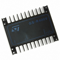
IC REG SW STEP DOWN 4A 5.1V-40V

GS-R400V

Manufacturer Part Number
GS-R400V
Description
IC REG SW STEP DOWN 4A 5.1V-40V
Manufacturer
STMicroelectronics
Series
GS-R400r
Type
Point of Load (POL) Non-Isolatedr
Datasheet

Specifications of GS-R400V

Output
5.1 ~ 40V
Number Of Outputs
1
Power (watts)
160W
Mounting Type
Through Hole
Voltage - Input
4 ~ 46V
Package / Case
Module
1st Output
5.1 ~ 40 VDC @ 4A
Size / Dimension
3.37" L x 2.64" W x 0.84" H (85.5mm x 67mm x 21.3mm)
Power (watts) - Rated
160W
Operating Temperature
-20°C ~ 85°C
Efficiency
90%
Output Voltage
5.1 V
Output Current
4 A
Input Voltage
4 V to 46 V
Switching Frequency
100 KHz
Operating Temperature Range
- 20 C to + 85 C
Mounting Style
SMD/SMT
Lead Free Status / RoHS Status
Lead free / RoHS Compliant
3rd Output
-
2nd Output
-
Lead Free Status / Rohs Status
Lead free / RoHS Compliant
Other names
497-8272
GS-R400V

Available stocks

Company
Part Number
Manufacturer
Quantity
Price
Part Number:
GS-R400V
Manufacturer:
MICRON
Quantity:
1 001
Part Number:
GS-R400V
Manufacturer:
ST
Quantity:
27
Part Number:
GS-R400V
Manufacturer:
ST
0
Part Number:
GS-R400V/2
Manufacturer:
ST
0
Part Number:
GS-R400VB
Manufacturer:
ST
Quantity:
530
Part Number:
GS-R400VB
Manufacturer:
ST
0
Part Number:
GS-R400VBEX
Manufacturer:
ST
0
FEATURES
DESCRIPTION
The GS-R400 series is a versatile family of high
current, high voltage step-down switching voltage
regulators.
The integral heatsink allows a large power handling
capability and it provides also an effective shielding
to minimize EMI.
SELECTION CHART
Note: The line regulation is measured at I
June 1994
ABSOLUTE MAXIMUM RATINGS
* GS-R405S only
GS-R405
GS-R412
GS-R415
GS-R424
GS-R405S
GS-R400V
GS-R400VB
Symbol
MTBF in excess of 200,000 hours
4A max output current
46V max input voltage
4V max drop-out voltage
Soft start
Remote logic inhibit/enable
Remote output voltage sense
Non-latching overload and short circuit protection
Crow-bar output overvoltage protection
T cop
Ordering
T stg
Number
I rt *
V i
Type
The load regulation is measured at V
For V
O
DC Input Voltage
Reset Output Sink Current
Storage Temperature Range
Operating Case Temperature Range
36V and I
12.0
15.0
24.0
5.1 to 40
5.1 to 40
Voltage
5.1
5.1
Output
(V)
o
2%
4%
4%
4%
2%
= 4A an external heatsink or forced ventilation are required.
Vo+4 to 46
Vo+4 to 46
Voltage
16 to 46
19 to 46
28 to 46
9 to 46
9 to 46
Input
(V)
out
in
=1A
=V
o
+8V and I
Parameter
25 to 100
25 to 100
(mVpp)
Output
Ripple
100
25
50
65
25
out
SWITCHING REGULATOR FAMILY
=1 to 3A
(mV/V)
Line
2
5
5
6
2
6
6
Regulation
20W TO 140W STEP-DOWN
20 to 90
20 to 90
(mV/A)
Load
20
40
60
90
20
Efficiency
70 to 90
70 to 90
GS-R400 Family
(%)
70
80
85
90
70
– 40 to +105
– 20 to +85
Fixed output voltage
Reset output
Progr. output voltage
Progr. output voltage and
current. Frequency synchr.
Value
48
20
Notes
"
"
"
Unit
mA
V
C
C
1/5

Related parts for GS-R400V

GS-R400V Summary of contents

Page 1

... GS-R415 15 GS-R424 24 GS-R405S 5 GS-R400V 5 Vo GS-R400VB 5 Vo Note: The line regulation is measured at I The load regulation is measured at V For V 36V and external heatsink or forced ventilation are required ABSOLUTE MAXIMUM RATINGS Symbol DC Input Voltage V i Reset Output Sink Current Storage Temperature Range ...

Page 2

... Return for input voltage source. 4 100kHz oscillator output connected to Sync (pin 6) input if the unit is a master and Oscillator 5 left open slave (GS-R400VB only). See fig. 5. Sync Synchronization input connected to the Oscillator output (pin 5) of the master (GS- 6 R400VB only). See fig. 5. ...

Page 3

... 5mA 10mA Case to ambient Thermal Characteristics The case-to-ambient thermal resistance of all the GS-R400 modules is about 5 C/W. This produces temperature increase of the module surface for 10W of internal power dissipation. Depending on the ambient temperature and/or on the power dissipation, an additional heatsink or forced ventilation may be required. ...

Page 4

... V can be adjusted between 5.1 and 40V. o Current Limiting Programming The GS-R400VB current limiting is programmed by using a resistor (see pin function table and fig. 4). Figure 1. Load Connection Figure 2. Remote Inhibit Operation 4/5 The value of the resistor is calculated by using the following formula: ...

Page 5

... SGS-THOMSON Microelectronics. Specification mentioned in this publication are subject to change without notice. This publication supersedes and replaces all information previously supplied. SGS-THOMSON Microelectronics products are not authorized for use as critical components in life support devices or systems without express written approval of SGS-THOMSON Microelectronics. ...

Related keywords