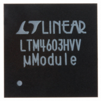
LTM4603HVEV#PBF Linear Technology, LTM4603HVEV#PBF Datasheet - Page 3

LTM4603HVEV#PBF
Manufacturer Part Number
LTM4603HVEV#PBF
Description
IC DC/DC UMODULE 6A 118-LGA
Manufacturer
Linear Technology
Series
µModuler
Type
Point of Load (POL) Non-Isolatedr
Datasheet
1.LTM4603HVEVPBF.pdf
(24 pages)
Specifications of LTM4603HVEV#PBF
Design Resources
LTM4603HV Spice Model
Output
0.6 ~ 5 V
Number Of Outputs
1
Power (watts)
30W
Mounting Type
Surface Mount
Voltage - Input
4.5 ~ 28 V
Package / Case
118-LGA
1st Output
0.6 ~ 5 VDC @ 6A
Size / Dimension
0.59" L x 0.59" W x 0.11" H (15mm x 15mm x 2.8mm)
Power (watts) - Rated
30W
Operating Temperature
-40°C ~ 85°C
Efficiency
93%
Lead Free Status / RoHS Status
Lead free / RoHS Compliant
3rd Output
-
2nd Output
-
Available stocks
Company
Part Number
Manufacturer
Quantity
Price
ELECTRICAL CHARACTERISTICS
temperature range, otherwise specifi cations are at T
SYMBOL
I
INTV
Output Specifi cations
I
ΔV
ΔV
V
f
ΔV
t
ΔV
t
I
Remote Sense Amp (Note 3)
V
CM Range
DIFFV
V
AV
GBP
SR
R
CMRR
S(VIN)
OUTDC
S
START
SETTLE
OUTPK
OUT(AC)
OSNS
OS
IN
OUT(LINE)
OUT(LOAD)
OUT(START)
OUTLS
V
V
OUT
OUT
CC
OUT
+
, V
OSNS
Range
–
PARAMETER
Input Supply Current
V
Output Continuous Current Range
(See Output Current Derating Curves
for Different V
Line Regulation Accuracy
Load Regulation Accuracy
Output Ripple Voltage
Output Ripple Voltage Frequency
Turn-On Overshoot,
TRACK/SS = 10nF
Turn-On Time, TRACK/SS = Open
Peak Deviation for Dynamic Load
Settling Time for Dynamic Load Step Load: 0% to 50% to 10% of Full Load
Output Current Limit
Common Mode Input Voltage Range V
Output Voltage Range
Input Offset Voltage Magnitude
Differential Gain
Gain Bandwidth Product
Slew Rate
Input Resistance
Common Mode Rejection Ratio
IN
= 12V, RUN > 2V
IN
, V
OUT
and T
A
)
A
= 25°C, V
CONDITIONS
V
V
V
No Load
V
V
V
I
I
C
V
C
V
Load: 0% to 50% to 0% of Full Load,
C
Sanyo POSCAP
C
V
V
OUT
OUT
IN
IN
IN
IN
OUT
OUT
OUT
OUT
OUT
OUT
OUT
OUT
IN
IN
OSNS
V
V
V
V
V
V
V
V
V
V
V
The
IN
IN
IN
IN
IN
IN
IN
IN
IN
IN
IN
= 12V, V
= 12V, V
= 5V, V
= 12V, V
= 12V, RUN > 2V
= 12V, DIFFV
= 0A, C
= 3A, V
= 1.5V, I
= 1.5V, I
= 2×, 100μF/X5R/Ceramic,
= 1.5V, I
= 2×, 100μF/X5R/Ceramic,
= 1.5V, I
= 2 × 22μF/Ceramic, 470μF, 4V
= 2×, 100μF/X5R/Ceramic
= 12V, V
= 5V, V
= 12V
= 5V
= 12V
= 5V
= 12V
= 5V
= 12V
= 12V, V
= 5V, V
+
●
IN
to GND
denotes the specifi cations which apply over the –40°C to 85°C
= 12V. Per typical application (front page) confi guration.
OUT
OUT
OUT
OUT
OUT
IN
OUT
OUT
OUT
OUT
OUT
OUT
OUT
OUT
= 12V, V
= 1.5V, I
= 2×, 100μF/X5R/Ceramic
= 1.5V, I
= 3.3V, I
= 1.5V
OUT
= 1.5V
= 1.5V
= 0A, V
= 0A to 6A, V
= 0A
= 1A Resisitive Load
= 1.5V
= 1.5V
Load = 100k
OUT
OUT
OUT
OUT
IN
= 1.5V
= 6A
= 4.5V to 28V
= 6A
= 6A
IN
= 12V
●
●
MIN
4.7
0
0
0
LTM4603HV
2.034
1000
0.85
1.78
TYP
100
0.5
0.7
10
10
20
20
35
35
25
20
5
8
8
1
3
2
INTV
INTV
MAX
0.25
1.25
5.3
0.3
6
CC
CC
– 1
UNITS
mV
mV
4603hvf
3
MHz
V/μs
kHz
mV
mV
mV
mV
V/V
mV
ms
ms
kΩ
P-P
P-P
dB
μs
%
%
A
A
A
V
A
A
A
V
V


