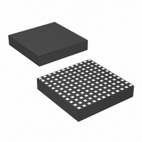
LTM4614IV#PBF Linear Technology, LTM4614IV#PBF Datasheet - Page 13

LTM4614IV#PBF
Manufacturer Part Number
LTM4614IV#PBF
Description
IC UMODULE DC/DC DUAL 4A 144LGA
Manufacturer
Linear Technology
Series
µModuler
Type
Point of Load (POL) Non-Isolatedr
Datasheet
1.LTM4614EVPBF.pdf
(20 pages)
Specifications of LTM4614IV#PBF
Design Resources
LTM4614 Spice Model
Output
0.8 ~ 5 V
Number Of Outputs
2
Power (watts)
12W
Mounting Type
Surface Mount
Voltage - Input
2.38 ~ 5.5 V
Package / Case
144-LGA
1st Output
0.8 ~ 5 VDC @ 4A
2nd Output
0.8 ~ 5 VDC @ 4A
Size / Dimension
0.59" L x 0.59" W x 0.11" H (15mm x 15mm x 2.8mm)
Power (watts) - Rated
12W
Operating Temperature
-40°C ~ 125°C
Efficiency
95%
Lead Free Status / RoHS Status
Lead free / RoHS Compliant
3rd Output
-
Available stocks
Company
Part Number
Manufacturer
Quantity
Price
APPLICATIONS INFORMATION
module temperature rise can be allowed. As an example in
Figure 7 the load current is de-rated to 3A for each chan-
nel with 0LFM at ~ 90°C and the power loss for both
channels at 5V to 1.2V at 3A output are ~1.5 watts. If the
90°C ambient temperature is subtracted from the 120°C
maximum junction temperature, then the difference of
30°C divided 1.5W equals a 20°C/W thermal resistance.
Table 2 specifi es a 15°C/W value which is close. Table 2
and Table 3 provide equivalent thermal resistances for
1.2V and 3.3V outputs with and without air fl ow and
4.5
4.0
3.5
3.0
2.5
2.0
1.5
1.0
0.5
4.5
4.0
3.5
3.0
2.5
2.0
1.5
1.0
0.5
Figure 7. 1.2V No Heat Sink (V
0
0
40
40
Figure 9. 3.3V No Heat Sink (V
200LFM NO HEAT SINK
200LFM NO HEAT SINK
50
50
400LFM NO HEAT SINK
400LFM NO HEAT SINK
AMBIENT TEMPERATURE (°C)
AMBIENT TEMPERATURE (°C)
0LFM NO HEAT SINK
60
60
0LFM NO HEAT SINK
70
70
80
80
90
90
100
100
110
110
IN
IN
4614 F07
4614 F09
= 5V)
= 5V)
120
120
heat sinking. The combine power loss for the two 4A
outputs can be summed together and multiplied by the
thermal resistance values in Tables 2 and 3 for module
temperature rise under the specifi ed conditions. The
printed circuit board is a 1.6mm thick four layer board
with 2 ounce copper for the two outer layers and 1 ounce
copper for the two inner layers. The PCB dimensions are
95mm × 76mm. The data sheet list the θ
pin) and θ
the Pin Confi guration diagram.
JC
4.5
4.0
3.5
3.0
2.5
2.0
1.5
1.0
0.5
4.5
4.0
3.5
3.0
2.5
2.0
1.5
1.0
0.5
0
0
(junction to case) thermal resistances under
40
40
Figure 8. 1.2V Heat Sink (V
Figure 10. 3.3V Heat Sink (V
50
50
AMBIENT TEMPERATURE (°C)
AMBIENT TEMPERATURE (°C)
60
60
200LFM HEAT SINK
400LFM HEAT SINK
400LFM HEAT SINK
200LFM HEAT SINK
70
70
0LFM HEAT SINK
0LFM HEAT SINK
80
80
90
90
100
100
IN
110
110
IN
LTM4614
= 5V)
4614 F10
4614 F08
= 5V)
120
JP
120
(junction to
13
4614fa


