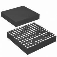
LTM4601AIV#PBF Linear Technology, LTM4601AIV#PBF Datasheet - Page 12

LTM4601AIV#PBF
Manufacturer Part Number
LTM4601AIV#PBF
Description
IC DC/DC UMODULE 12A 133-LGA
Manufacturer
Linear Technology
Series
µModuler
Type
Point of Load (POL) Non-Isolatedr
Datasheet
1.LTM4601AEVPBF.pdf
(28 pages)
Specifications of LTM4601AIV#PBF
Design Resources
LTM4601A Spice Model
Output
0.6 ~ 5 V
Number Of Outputs
1
Power (watts)
60W
Mounting Type
Surface Mount
Voltage - Input
4.5 ~ 20V
Package / Case
133-LGA
1st Output
0.6 ~ 5 VDC @ 12A
Size / Dimension
0.59" L x 0.59" W x 0.11" H (15mm x 15mm x 2.8mm)
Power (watts) - Rated
60W
Operating Temperature
-40°C ~ 85°C
Efficiency
95%
Dc To Dc Converter Type
Step Down
Pin Count
133
Input Voltage
20V
Output Voltage
0.6 to 5V
Switching Freq
850kHz
Output Current
12A
Package Type
LGA
Output Type
Adjustable
Switching Regulator
Yes
Load Regulation
1%
Line Regulation
0.3%
Mounting
Surface Mount
Input Voltage (min)
4.5V
Operating Temperature Classification
Industrial
Lead Free Status / RoHS Status
Lead free / RoHS Compliant
3rd Output
-
2nd Output
-
Lead Free Status / Rohs Status
Compliant
Available stocks
Company
Part Number
Manufacturer
Quantity
Price
APPLICATIONS INFORMATION
LTM4601A/LTM4601A-1
Multiphase operation with multiple LTM4601A devices
in parallel will lower the effective output ripple current
due to the interleaving operation of the regulators. For
example, each LTM4601A’s inductor current of a 12V to
2.5V multiphase design can be read from the Inductor
Ripple Current vs Duty Cycle graph (Figure 3). The large
ripple current at low duty cycle and high output voltage
12
12
10
8
6
4
2
0
0
Figure 3. Inductor Ripple Current vs Duty Cycle
Figure 4. Normalized Output Ripple Current vs Duty Cycle, Dlr = V
20
DUTY CYCLE (V
40
OUT
/V
IN
60
)
1.00
0.95
0.90
0.85
0.80
0.75
0.70
0.65
0.60
0.55
0.50
0.45
0.40
0.35
0.30
0.25
0.20
0.15
0.10
0.05
0
0.1 0.15 0.2 0.25
4601A F03
80
2.5V OUTPUT
5V OUTPUT
1.8V OUTPUT
1.5V OUTPUT
1.2V OUTPUT
3.3V OUTPUT WITH
130k ADDED FROM
V
5V OUTPUT WITH
100k ADDED FROM
f
SET
OUT
TO GND
TO f
0.3
SET
0.35
0.4 0.45 0.5 0.55 0.6 0.65 0.7 0.75 0.8 0.85 0.9
DUTY CYCLE (V
can be reduced by adding an external resistor from f
ground which increases the frequency. If the duty cycle is
DC = 2.5V/12V = 0.21, the inductor ripple current for 2.5V
output at 21% duty cycle is ~6A in Figure 3.
Figure 4 provides a ratio of peak-to-peak output ripple cur-
rent to the inductor current as a function of duty cycle and
the number of paralleled phases. Pick the corresponding
duty cycle and the number of phases to arrive at the correct
output ripple current ratio value. If a 2-phase operation is
chosen at a duty cycle of 21%, then 0.6 is the ratio. This
0.6 ratio of output ripple current to inductor ripple of 6A
equals 3.6A of effective output ripple current. Refer to Ap-
plication Note 77 for a detailed explanation of output ripple
current reduction as a function of paralleled phases.
The output voltage ripple has two components that are
related to the amount of bulk capacitance and effective
series resistance (ESR) of the output bulk capacitance.
Therefore, the output voltage ripple can be calculated with
the known effective output ripple current. The equation:
ΔV
OUT(P-P)
O
/V
IN
)
O
T/L
≈ (ΔI
I
, Dlr = Each Phase’s Inductor Current
L
/(8 • f • m • C
1-PHASE
2-PHASE
3-PHASE
4-PHASE
6-PHASE
4601A F04
OUT
) + ESR • ΔI
L
), where f
SET
4601afb
to


