LSN-T/10-D12-C Murata Power Solutions Inc, LSN-T/10-D12-C Datasheet - Page 6
LSN-T/10-D12-C
Manufacturer Part Number
LSN-T/10-D12-C
Description
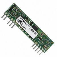
CONV DC/DC 10A 0.75-5.25V SIP
Manufacturer
Murata Power Solutions Inc
Type
Point of Load (POL) Non-Isolatedr
Series
LSNr
Datasheet
1.LSN-T10-D12N-C.pdf
(12 pages)
Specifications of LSN-T/10-D12-C
Number Of Outputs
1
Output
0.75 ~ 5.25V
Power (watts)
51W
Mounting Type
Through Hole
Voltage - Input
10 ~ 14V
Package / Case
11-SIP Module (10 Leads)
1st Output
0.75 ~ 5.25 VDC @ 10A
Size / Dimension
2.00" L x 0.34" W x 0.55" H (50.8mm x 8.6mm x 14mm)
Power (watts) - Rated
51W
Operating Temperature
-40°C ~ 85°C
Efficiency
96.5%
Approvals
EN, UL
Output Power
53 W
Input Voltage Range
10.8 V to 13.2 V
Input Voltage (nominal)
12 V
Output Voltage (channel 1)
1.2 V to 5.25 V
Output Current (channel 1)
10 A
Package / Case Size
SIP
Output Type
Low Voltage
Output Voltage
0.75 V to 5.25 V
Input Voltage
10V To 14V
Power Rating
51W
Output Current
10A
Supply Voltage
12V
Dc / Dc Converter Case Style
SIP
Dc/dc Converter Mounting
Through Hole
Svhc
No SVHC (15-Dec-2010)
Rohs Compliant
Yes
Product
Non-Isolated / POL
Lead Free Status / RoHS Status
Lead free / RoHS Compliant
3rd Output
-
2nd Output
-
Lead Free Status / Rohs Status
Lead free / RoHS Compliant
Other names
811-1807-5
Available stocks
Company
Part Number
Manufacturer
Quantity
Price
Company:

Part Number:
LSN-T/10-D12-C
Manufacturer:
Murata Power Solutions Inc
Quantity:
135


Pre-Biased Startup
Newer systems with multiple power voltages have an additional problem
besides startup sequencing. Some sections have power already partially ap-
plied (possibly because of earlier power sequencing) or have leakage power
present so that the DC/DC converter must power up into an existing voltage.
This power may either be stored in an external bypass capacitor or supplied
by an active source.
This “pre-biased” condition can also occur with some types of program-
mable logic or because of blocking diode leakage or small currents passed
through forward biased ESD diodes. Conventional DC/DC’s may fail to start up
correctly if there is output voltage already present. And some external circuits
are adversely affected when the low side MOSFET in a synchronous rectifier
converter sinks current at start up.
The LSN2 series includes a pre-bias startup mode to prevent these initializa-
tion problems. Essentially, the converter acts as a simple buck converter until
the output reaches its set point voltage at which time it converts to a synchro-
nous rectifier design. This feature is variously called “monotonic” because
the voltage does not decay (from low side MOSFET shorting) or produce a
negative transient once the input power is applied and the startup sequence
begins.
Output Adjustments
The LSN-T/10-D12J includes an output adjustment and trimming function
which is fully compatible with competitive units. The output voltage may be
varied using a single trim resistor from the Trim input to Power Common or an
external DC trim voltage applied between the Trim input and Power Common.
For resistor trim adjustments, be sure to use a precision low-tempco resistor
(±100 ppm/°C) mounted close to the converter with short leads. Since the
output accuracy is ±2% (typical), you may need to vary this resistance slightly.
For adjustments using an external voltage reference, the equivalent input im-
pedance looking in to the Trim input is approximately 5,000 Ohms. Therefore
you may have to compensate for this in the source resistance of your external
reference. Although filtered internally, the Trim input is sensitive and therefore
susceptible to noise pickup with longer leads. Consider adding a small bypass
capacitor, 0.1μF or larger mounted adjacent to the converter between the Trim
and Power Common if there is noise in the application.
The Trim input voltage range is offset against the 0.7 Volt reference of the
PWM. Also note that the Trim input is inverting (lower trim voltage produces
higher output voltage and vice versa). Do not exceed the voltage range or
maximum power rating.
www.murata-ps.com
Single Adjustable Output, Non-isolated, 12Vin, 10A, SIP, DC/DC Converters
D12 Models Resistor Trim Equation:
D12 Models Voltage Trim Equation:
The D12 fixed trim voltages to set the output voltage are:
R
V
V
(kΩ)
V
where V
(V)
TRIM
where V
TRIM
OUT
OUT
0.7525V 1.0V
0.7525V
Open
Open
R
O
O
V
TRIM
is the desired output voltage.
is the desired output voltage.
TRIM
(Ω) = _____________ –1000
41.424 22.46 13.05 9.024 7.417 5.009 3.122 1.472
0.6835 0.670 0.650 0.630 0.617 0.583 0.530 0.4166
(in Volts) = 0.7 –(0.0667 x (V
1.0V
Technical enquiries email: sales@murata-ps.com, tel:
V
1.2V
1.2V
O
10500
– 0.7525
Trim Connections
1.5V
1.5V
1.8V
1.8V
LSN-T/10-D12
O
– 0.7525))
2V
2V
LSN-T10-D12.B01 Page 6 of 12
2.5V
2.5V
3.3V
3.3V
+1 508 339 3000
5V
5V
Related parts for LSN-T/10-D12-C
Image
Part Number
Description
Manufacturer
Datasheet
Request
R

Part Number:
Description:
CONV DC/DC 10A 0.75-5.25V SIP
Manufacturer:
Murata Power Solutions Inc
Datasheet:

Part Number:
Description:
DC/DC TH 10A-Variable Non-iso
Manufacturer:
Murata Power Solutions Inc
Part Number:
Description:
DC/DC TH 10A-Variable Non-iso
Manufacturer:
Murata Power Solutions Inc

Part Number:
Description:
DC/DC TH 10A-Variable Non-iso
Manufacturer:
Murata Power Solutions Inc
Part Number:
Description:
DC/DC TH 10A-Variable Non-iso
Manufacturer:
Murata Power Solutions Inc

Part Number:
Description:
DC/DC TH 16A 12 To 0.75-5.0V Non-Iso
Manufacturer:
Murata Power Solutions Inc
Datasheet:
Part Number:
Description:
DC/DC TH 16A 12 To 0.75-5.0V Non-Iso
Manufacturer:
Murata Power Solutions Inc
Datasheet:
Part Number:
Description:
DC/DC TH 16A 12 To 0.75-5.0V Non-Iso
Manufacturer:
Murata Power Solutions Inc
Datasheet:

Part Number:
Description:
DC/DC TH 16A W3 To 0.75-3.3V Non-Iso
Manufacturer:
Murata Power Solutions Inc
Datasheet:
Part Number:
Description:
DC/DC TH 16A W3 To 0.75-3.3V H Non-Iso
Manufacturer:
Murata Power Solutions Inc
Datasheet:

Part Number:
Description:
Transformers 5Vin 5Vout 200mA 4000Vdc 1:1.33 turn
Manufacturer:
Murata Power Solutions Inc
Datasheet:
Part Number:
Description:
POWER SUPPLY
Manufacturer:
Murata Power Solutions Inc
Datasheet:

Part Number:
Description:
DPM LED MINI 2VDC 3.5DIG LP RED
Manufacturer:
Murata Power Solutions Inc
Datasheet:

Part Number:
Description:
CONV DC/DC 1W 5VIN 5VOUT SIP SGL
Manufacturer:
Murata Power Solutions Inc
Datasheet:

Part Number:
Description:
CONV DC/DC 1W 5VIN 3.3V SIP SGL
Manufacturer:
Murata Power Solutions Inc
Datasheet: