TLRBP TDK Corporation, TLRBP Datasheet
TLRBP
Specifications of TLRBP


Related parts for TLRBP

TLRBP Summary of contents
Page 1
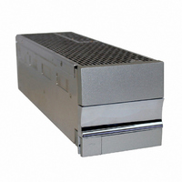
TLR5 - COMPACT DC POWER SYSTEM Installation, Operation, and Maintenance Manual TLR5 July 2005 Version A3 ...
Page 2
Table of Contents 1) Safety and Recommended Practices General practices 1.1 FCC Compliance Statement 1.2 Note 1.2.1 Warning 1.2.2 ICES-003 Class B notice 1.2.3 2) Product Section Heat Dissipation 2.1 AC Requirements 2.2 AC input circuit breaker sizing 2.2.1 AC ...
Page 3
Safety and Recommended Practices 1.1 General practices For use in restricted access locations only. Suitable for mounting on concrete or other non-combustible surfaces This product accepts an AC Voltage between 100 and 240 VAC Hz, and ...
Page 4
TLR5-S S ERIES POWER SYSTEM 1.2 FCC Compliance Statement 1.2.1 Note This device complies with Part 15 of FCC Rules. Operation is subject to the following two condi- tions: 1. This device may not cause harmful interference, and 2. This ...
Page 5
ICES Class B Notice This Class B digital apparatus complies with Canadian ICES-003. Cet appareil numérique de la classe B est conforme à la norme NMB-003 du Canada. 2 Product Section 2.1 Heat Dissipation The following table ...
Page 6
TLR5-S S ERIES POWER SYSTEM 2.2 AC Requirements 2.2.1 AC input circuit breaker sizing Table 4 shows the required input voltages for the available power modules. The power modules under wide line (WL) can be connected to a nominal input ...
Page 7
AC Input Types This system utilizes a single, dual, or individual feed AC architecture (as shown in Figure 1, Figure 2, & Figure 3) via a rear AC terminal block. 2.2.2.1 Single Feed AC Line 1 Figure 1 - ...
Page 8
TLR5-S S ERIES POWER SYSTEM 2.2.2.2 Dual feed AC Line 1 AC Line 2 Figure 2 - Dual Feed AC Wiring Architecture A dual feed architecture powers three power modules on AC feed 1 and two power module on AC ...
Page 9
AC Line 1 AC Line 2 AC Line 3 AC Line 4 AC Line 5 Figure 3 - Individual Feed AC Wiring Architecture An individual feed architecture powers one power module on each AC feed. Connect the AC source that ...
Page 10
TLR5-S S ERIES POWER SYSTEM Recommended AC Circuit Breaker & Wire Sizes (12V system) Number of Power Minimum Model Number Modules on Input of Power AC Feed Voltage Module 90 TL50012 180 TL50012 1 90 TL75012 180 TL75012 90 TL50012 ...
Page 11
Recommended AC Circuit Breaker & Wire Sizes (24V system) Number of Power Minimum Model Number Modules on Input of Power AC Feed Voltage Module 90 TL50024 180 TL50024 1 90 TL100024 180 TL100024 180 TL150024 90 TL50024 180 TL50024 2 ...
Page 12
TLR5-S S ERIES POWER SYSTEM Recommended AC Circuit Breaker & Wire Sizes (48V system) Number of Power Minimum Model Number Modules on Input of Power AC Feed Voltage Module 90 TL50048 180 TL50048 90 TL100048 1 180 TL100048 180 TL150048 ...
Page 13
AC lugs The table below lists part numbers for some lugs you can use to attach your AC wire to the single and dual AC terminal blocks and ground studs. Use the #8 lugs for AC terminal block connec- ...
Page 14
TLR5-S S ERIES POWER SYSTEM 2.3.1 DC circuit 1 Figure Wiring Diagram (Circuit #1) Each system is equipped with two double hole lug DC connection pads located behind the rear panel as shown in Figure 10. Select ...
Page 15
Minumum Recommended DC AWG for 90°C Cabling Total Power Module Current Rating ( 100 125 150 175 200 225 250 300 * For wire sizes less than 15 A not covered in ...
Page 16
TLR5-S S ERIES POWER SYSTEM 2.4 Torque settings Table 11 shows the recommended torque settings for all mechanical and electrical connections according to screw or nut size. Not all screw sizes may be present on a particular rack. Recommended Torque ...
Page 17
Power Plant Mounting and Wiring 5.1 Mechanical mounting This equipment is intended for normal operations and installed in a standard 19" telecommunications rack recommended that one person lift the rack into place while anoth- ...
Page 18
TLR5-S S ERIES POWER SYSTEM 5.2 AC input Knockouts are provided to route AC cables to the proper connections on the single and dual feed shelves. Remove the cutout and place the provided cord grip in the knockout to provide ...
Page 19
AC ground Figure 7 - Single AC feed When ready to power up, plug in the AC cord into the proper receptacle or turn on the AC breaker. 5.2.2 Dual Feed For 110 Vac service, connect your first line/hot to ...
Page 20
TLR5-S S ERIES POWER SYSTEM When ready to power up, plug in the AC cord into the proper receptacle or turn on the AC breaker. 5.2.3 Individual Feed The TLR5 comes with two different types of Individual AC feeds. The ...
Page 21
DC output DC connections are accomplished via the two rear bulk output connections as shown in Figure 10. Connections are made with double hole lugs with ¼" holes and 5/8" centers. Select wire and lug sizes according to Section ...
Page 22
TLR5-S S ERIES POWER SYSTEM 5.4 Reference ground The polarity on this rack is universal. Connect your reference ground to either the negative out- put or positive output depending on the desired polarity. The connection is a double ¼" studs ...
Page 23
Alarm and Signal Interconnections J1 Wire Description Pin Color 20 BLK Shelf Bias: A regulated 12V/100ma bias supply. Referenced to Pin 10. 19 RED SCL clock line. Referenced to Pin 10 RED/WHT SDA data ...
Page 24
TLR5-S S ERIES POWER SYSTEM 6 Test and Turn 6.1 Power up Once all AC and DC connections have been secured and checked, install each power module sequentially by sliding and latching each power module into a rack ...
Page 25
Troubleshooting 7.1 Problems and Solutions The modular, plug-n-play nature of this plant makes diagnostics and repair very easy. Make sure that all power modules are properly seated and latched into their respective slots. Make sure that all power and ...
Page 26
TLR5-S S ERIES POWER SYSTEM 7.2 Short circuit & Current Limit I can be adjusted up to +105% of the rated current of the power module. The system voltage will Limit remain constant which point the ...
Page 27
Installationsanleitung (German Installation) Eingangsspannung (Voltage): Netzteile fuer (100V - 240V) TL50048 TL50024 TL50012 TL75012 TL100048 TL100024 Eingangsstrom (Current ): 75A Nennfrequenz (Frequency): 50/60Hz Modellnummer (Modell No Abmessungen sind nur zur Referenz (Dimensions are for reference only): ...