HW-FLYLEADS Xilinx Inc, HW-FLYLEADS Datasheet - Page 17
HW-FLYLEADS
Manufacturer Part Number
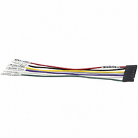
HW-FLYLEADS
Description
LEAD WIRES FLYING CABLE III/IV
Manufacturer
Xilinx Inc
Datasheet
1.HW-FLYLEADS.pdf
(20 pages)
Specifications of HW-FLYLEADS
Accessory Type
Parallel Cable
For Use With/related Products
Xilinx FPGA, CPLDS, Platform Flash PROMs, XC18V00 PROMs, System ACE MPM
Lead Free Status / RoHS Status
Contains lead / RoHS non-compliant
Other names
122-1473
Available stocks
Company
Part Number
Manufacturer
Quantity
Price


Table 5: SS/JTAG/SPI Port: 14-Pin Ribbon Cable Connector (Cont’d)
Platform Cable USB Operating Characteristics
Table 6: Absolute Maximum Ratings
Table 7: Recommended DC Operating Conditions
DS300 (v3.2) May 14, 2008
Product Specification
Notes:
1.
2.
3.
Notes:
1.
2.
3.
1, 3, 5, 7,
9, 11, 13
Number
Ribbon
Cable
Symbol
Symbol
I
All odd pins (1, 3, 5, 7, 9, 11, and 13) should be connected to digital ground on the target end of the ribbon cable. Minimum crosstalk is
achieved when using all grounds.
The listed SPI pin names match those of SPI flash memories from STMicroelectronics. Pin names of compatible SPI devices from other
vendors can be different. Consult the vendor's SPI device data sheet for corresponding pin names.
Caution! The PROG_B pin of the FPGA, which is connected to a target SPI device, must be asserted Low during SPI programming to
ensure the FPGA does not contend with the SPI programming operation.
The target reference voltage must be regulated and must not have a current-limiting resistor in series with the V
Operating at Hi-Speed on a USB 2.0 port. The I
DLC9 cable model I
Operating at full-speed on a low-power USB 1.1 port. The I
legacy DLC9 cable model I
Exposure to Absolute Maximum Rating conditions for extended periods of time can affect product reliability. These are stress ratings only and
functional operation of the product at these or any other condition beyond those listed under Recommended Operating Conditions is not implied.
V
V
V
V
T
I
I
I
CCSU
I
I
V
V
V
V
V
REF
CC1
CC2
OUT
REF
V
T
T
REF
REF
Bus
SIG
Bus
OH
OH
OL
OL
A
IH
A
IL
Configuration
Slave-Serial
R
USB Port Supply Voltage
Target Reference Voltage
Target Supply Current
Operating Temperature
Storage Temperature
High-Level Output Voltage
Low-Level Output Voltage
High-Level Output Voltage
Low-Level Output Voltage
High-Level Input Voltage
Low-Level Input Voltage
USB Port Supply Voltage
Target Reference Voltage
Target Supply Current
Operating Temperature
Dynamic Current
Dynamic Current
Suspend Current
DC Output Current (TCK_CCLK_SCK,
TMS_PROG_SS, TDI_DIN_MOSI,
and INIT)
Mode
–
CC1
value is 230 mA.
Description
Configuration
Description
CC2
Mode
JTAG
(1)
(2)
value is 98 mA.
–
Programming
SPI
Mode
CC1
–
(2)
value in the table applies to the DLC9G and legacy DLC9LP cable models. The legacy
V
V
V
V
V
V
V
V
V
V
V
REF
REF
REF
REF
REF
REF
REF
REF
BUS
BUS
BUS
www.xilinx.com
CC2
= 3.30V
= 3.3V; I
= 3.3V; I
= 1.5V; I
= 1.5V; I
= 1.5V
= 1.5V
Type
= 5.25V
= 5.25V; TCK = 24 MHz
= 5.25V; TCK = 6 MHz
= 5.25V
–
table value applies to the DLC9G and legacy DLC9LP cable models. The
Conditions
Conditions
Digital Ground.
OH
OH
OH
OH
= –8 mA
= 8 mA
= –8 mA
= 8 mA
(1)
Description
4.00
Min
–40
1.5
3.0
1.3
1.2
1
0
Value
5.25
6.00
110
350
+24
70
90
75
REF
Platform Cable USB
Max
5.25
5.00
+85
0.4
0.4
0.4
18
70
pin.
Units
Units
mA
mA
mA
mA
mA
μA
o
o
o
V
V
V
V
V
V
V
V
V
V
C
C
C
17
Related parts for HW-FLYLEADS
Image
Part Number
Description
Manufacturer
Datasheet
Request
R

Part Number:
Description:
BOARD ADAPTER AND FLY LEADS
Manufacturer:
Xilinx Inc
Datasheet:

Part Number:
Description:
CONN HEADER .25" VERT 4POS T/H
Manufacturer:
Samtec Inc
Part Number:
Description:
CONN HEADER .25" VERT 4POS SMD
Manufacturer:
Samtec Inc
Part Number:
Description:
CONN HEADER .25" VERT 10POS SMD
Manufacturer:
Samtec Inc
Part Number:
Description:
Conn Board Stacker HDR 28 POS 2.54mm Solder ST SMD
Manufacturer:
Samtec Inc
Datasheet:
Part Number:
Description:
CONN BOARD STACK 28POS SMD
Manufacturer:
Samtec Inc
Datasheet:

Part Number:
Description:
IC CPLD .8K 36MCELL 44-VQFP
Manufacturer:
Xilinx Inc
Datasheet:

Part Number:
Description:
IC CPLD 72MCRCELL 10NS 44VQFP
Manufacturer:
Xilinx Inc
Datasheet:

Part Number:
Description:
IC CPLD 1.6K 72MCELL 64-VQFP
Manufacturer:
Xilinx Inc
Datasheet:

Part Number:
Description:
IC CR-II CPLD 64MCELL 44-VQFP
Manufacturer:
Xilinx Inc
Datasheet:

Part Number:
Description:
IC CPLD 1.6K 72MCELL 100-TQFP
Manufacturer:
Xilinx Inc
Datasheet:

Part Number:
Description:
IC CR-II CPLD 64MCELL 56-BGA
Manufacturer:
Xilinx Inc
Datasheet: