TOOLSTICKDA Silicon Laboratories Inc, TOOLSTICKDA Datasheet - Page 3
TOOLSTICKDA
Manufacturer Part Number
TOOLSTICKDA
Description
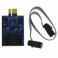
TOOLSTICK DEBUG ADAPTER
Manufacturer
Silicon Laboratories Inc
Series
ToolStickr
Datasheet
1.TOOLSTICKDA.pdf
(6 pages)
Specifications of TOOLSTICKDA
Accessory Type
*
Interface Type
USB
Operating Supply Voltage
2.7 V to 3.6 V
Features
Provides Interface Between PC?S USB Port & Target Device?s In-System Debug/Programming Circuitry
Convert From
USB
Rohs Compliant
Yes
Lead Free Status / RoHS Status
Contains lead / RoHS non-compliant
For Use With/related Products
ToolStick Base adapter
Lead Free Status / Rohs Status
Lead free / RoHS Compliant
For Use With
ToolStick Base Adapter
Lead Free Status / RoHS Status
Lead free / RoHS Compliant, Contains lead / RoHS non-compliant
Other names
336-1347
Available stocks
Company
Part Number
Manufacturer
Quantity
Price
Company:

Part Number:
TOOLSTICKDA
Manufacturer:
Silicon Labs
Quantity:
135


4. Hardware Setup using a ToolStick Debug Adapter
Configure the ToolStick Debug Adapter
1. Place the jumper J1 in the appropriate position for the I/O voltage of the Target Board being used. Connect pins
2. If the Target Board will be powered from the ToolStick Debug Adapter, place a jumper on header J2. If the
Note: Powering the Target Board from the ToolStick Debug Adapter and a separate power supply at the same time could
Connect the ToolStick Debug Adapter to the Target Board as shown in Figure 5.
1. If not already assembled, insert the ToolStick Debug Adapter into a ToolStick Base Adapter.
2. Connect the 10-pin ribbon cable from the ToolStick Debug Adapter to the Target Board debug header.
3. Connect one end of the USB cable to the USB connector on the ToolStick Debug Adapter.
4. Connect the other end of the USB cable to a USB port on the PC that will run the Silicon Laboratories IDE.
5. Connect the AC/DC power adapter to the power jack on the target board, or configure the board to receive
Notes:
1 and 2 (V
Target Board will be separately powered, ensure that no jumper is installed on header J2.
power from the ToolStick Debug Adapter (see the Target Board Kit User’s Guide for configuration options).
Use the Reset button in the IDE to reset the target when connected using a ToolStick Debug Adapter.
Remove power from the target board and the ToolStick Debug Adapter before connecting or disconnecting the
ribbon cable from the target board. Connecting or disconnecting the cable when the devices have power can
damage the device and/or the ToolStick Debug Adapter.
cause damage to the ToolStick Base Adapter and/or the Target Board.
REG
and V
Figure 5. Hardware Setup Using a ToolStick Debug Adapter
IO
) for 2.5 V I/O or connect pins 2 and 3 (V
Base Adapter
Figure 4. ToolStick Debug Adapter Jumpers
ToolStick
Adapter
Debug
J1
Rev. 0.1
To olSt ick Debug Adapter
J2
J3
DD
and V
Target Board
P2
IO
) for 3.3 V I/O.
3
Related parts for TOOLSTICKDA
Image
Part Number
Description
Manufacturer
Datasheet
Request
R

Part Number:
Description:
NiCd - Nickel Cadmium Battery 9.6V 1500MAH
Manufacturer:
FDK Batteries (Formerly Sanyo)
Part Number:
Description:
Battery; Tool; NiCAD; 2.4V; 2400mah
Manufacturer:
Dantona Industries, Inc.
Datasheet:
Part Number:
Description:
Battery, Tool, Dewalt Compatable Replacement Battery, 18v, 1500mAh, Nicad
Manufacturer:
Dantona Industries, Inc.
Datasheet:
Part Number:
Description:
MILWAUKEE CORDLESS DRILL REPLACEMENT BATTERY, 12V, 1.3A
Manufacturer:
MILWAUKEE TOOL

Part Number:
Description:
TOOL-125, 12, 2400, NI-CD, MILWAUKEE:
Manufacturer:
DANTONA INDUSTRIES
Part Number:
Description:
Unspecified Battery types 2.4V 2500mAh EY9021
Manufacturer:
Unspecified
Part Number:
Description:
NiCd - Nickel Cadmium Battery 18V 2400mAh DeWalt Replacement
Manufacturer:
Unspecified
Part Number:
Description:
NiCd - Nickel Cadmium Battery 18V 2200mah
Manufacturer:
Unspecified
Part Number:
Description:
NiCd - Nickel Cadmium Battery 2.4V 1500mAh EY9021
Manufacturer:
Unspecified

Part Number:
Description:
SMD/C�/SINGLE-ENDED OUTPUT SILICON OSCILLATOR
Manufacturer:
Silicon Laboratories Inc
Part Number:
Description:
Manufacturer:
Silicon Laboratories Inc
Datasheet:
Part Number:
Description:
N/A N/A/SI4010 AES KEYFOB DEMO WITH LCD RX
Manufacturer:
Silicon Laboratories Inc
Datasheet:
Part Number:
Description:
N/A N/A/SI4010 SIMPLIFIED KEY FOB DEMO WITH LED RX
Manufacturer:
Silicon Laboratories Inc
Datasheet: