TWR-PROTO Freescale Semiconductor, TWR-PROTO Datasheet
TWR-PROTO
Manufacturer Part Number
TWR-PROTO
Description
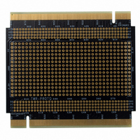
TOWER SYSTEM PROTO
Manufacturer
Freescale Semiconductor
Specifications of TWR-PROTO
Accessory Type
ProtoBoard
Product
Breadboards / Protoboards
Description/function
Prototyping Module
Dimensions
90 mm x 80 mm
Development Tool Type
Hardware / Software - Eval/Demo Board
Kit Contents
Board, Cable, CD
Leaded Process Compatible
Yes
Mcu Supported Families
Tower Development System
Rohs Compliant
Yes
For Use With/related Products
Freescale Tower System
Lead Free Status / RoHS Status
Lead free / RoHS Compliant


TWR-PROTO Module Errata
Issue:
The following issue has been discovered with the secondary PCI edge connector on the
TWR-PROTO Rev. A boards. The Power Sense signal on the secondary side of the edge
connector is tied directly to the 3.3V signals on both the primary and secondary edge
connectors. The Power Sense Signal is located on Pin B4 on both the Primary and
Secondary edge connectors.
The Power Sense signal is also connected to B4 and D4 on the TWR-PROTO Primary
and Secondary Connector Signal Access areas. The D4 (Secondary Connector Signal
Access) is connected directly to the 3.3V signals.
Impact:
This issue has the potential of connecting the 5V Power Sense signal to the 3.3V power
supply if the TWR-PROTO module’s secondary edge connector is inserted into a
functional TWR-ELEV.
The following cases will cause the issue to manifest and should be avoided:
Solution:
The Power Sense signal on the secondary edge connector should be cut. This will isolate
the 3.3V rail from the 5V Power Sense signal. Note that D4 in the Secondary Connector
Signal Access will no longer be connected to the Power Sense signal and should be
considered a 3.3V signal.
1) The TWR-PROTO module will inserted backwards into a basic Tower system,
2) The TWR-PROTO module is used with two function elevators. To fully utilize
consisting of at minimum a TWR-PROTO and TWR-ELEV’s (Functional and
Dummy). In this scenario “backwards” is defined at the TWR-PROTO module’s
secondary edge connector being inserted into the functional elevator and the
primary edge connector being inserted into the dummy elevator.
all functions of certain MCU and MPU Tower module two functional elevators
can be used to expand the secondary backplane to all Tower modules in the
Tower System. The TWR-PROTO Rev A. board should not be used in a Tower
System with dual functional elevators.
Related parts for TWR-PROTO
Image
Part Number
Description
Manufacturer
Datasheet
Request
R

Part Number:
Description:
LCD MODULE FOR TWR SYSTEM
Manufacturer:
Freescale Semiconductor
Datasheet:

Part Number:
Description:
TOWER ELEVATOR BOARDS HARDWARE
Manufacturer:
Freescale Semiconductor
Datasheet:

Part Number:
Description:
TOWER SERIAL I/O HARDWARE
Manufacturer:
Freescale Semiconductor
Datasheet:

Part Number:
Description:
MEMORY MODULE FOR TWR SYSTEM
Manufacturer:
Freescale Semiconductor
Datasheet:

Part Number:
Description:
Manufacturer:
Freescale Semiconductor, Inc
Datasheet:
Part Number:
Description:
Manufacturer:
Freescale Semiconductor, Inc
Datasheet:
Part Number:
Description:
Manufacturer:
Freescale Semiconductor, Inc
Datasheet:
Part Number:
Description:
Manufacturer:
Freescale Semiconductor, Inc
Datasheet:
Part Number:
Description:
Manufacturer:
Freescale Semiconductor, Inc
Datasheet:
Part Number:
Description:
Manufacturer:
Freescale Semiconductor, Inc
Datasheet:
Part Number:
Description:
Manufacturer:
Freescale Semiconductor, Inc
Datasheet:
Part Number:
Description:
Manufacturer:
Freescale Semiconductor, Inc
Datasheet:
Part Number:
Description:
Manufacturer:
Freescale Semiconductor, Inc
Datasheet:
Part Number:
Description:
Manufacturer:
Freescale Semiconductor, Inc
Datasheet:
Part Number:
Description:
Manufacturer:
Freescale Semiconductor, Inc
Datasheet:
TWR-PROTO Summary of contents
Page 1
... The Power Sense Signal is located on Pin B4 on both the Primary and Secondary edge connectors. The Power Sense signal is also connected to B4 and D4 on the TWR-PROTO Primary and Secondary Connector Signal Access areas. The D4 (Secondary Connector Signal Access) is connected directly to the 3.3V signals. ...
Page 2
... Figure 1 shows the impacted area of the TWR-PROTO module. The B4 edge connector pin on the secondary side is connected to B3 edge connector pin and C3, C4, D3 the Secondary Connector Signal Access. Figure 2 - TWR-PROTO - Modified Board Image Figure 2 show a TWR-PROTO board that has been correctly modified to isolate the B4 edge connector pin from 3.3V signals. ...