AC244006 Microchip Technology, AC244006 Datasheet - Page 29
AC244006
Manufacturer Part Number
AC244006
Description
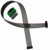
KIT MPLAB REAL ICE TRACE
Manufacturer
Microchip Technology
Datasheet
1.AC244006.pdf
(72 pages)
Specifications of AC244006
Accessory Type
Interface Board
Features
Instruction Trace Capability, Polarized Interface
For Use With
PIC32MX Plug-in Modules
Lead Free Status / RoHS Status
Lead free / RoHS Compliant
For Use With/related Products
PIC32
Lead Free Status / RoHS Status
Lead free / RoHS Compliant
Available stocks
Company
Part Number
Manufacturer
Quantity
Price
Company:

Part Number:
AC244006
Manufacturer:
Microchip Technology
Quantity:
135


4.7
4.8
© 2006 Microchip Technology Inc.
SETTING THE EMULATOR AS THE DEBUGGER OR PROGRAMMER
SETTINGS DIALOG
Select Debugger>Select Tool>MPLAB REAL ICE to choose the MPLAB REAL ICE
in-circuit emulator as the debug tool. The Debugger menu and MPLAB IDE toolbar will
change to display debug options once the tool is selected. Also, the Output window will
open and messages concerning ICE status and communications will be displayed on
the MPLAB REAL ICE tab.
Select Programmer>Select Programmer>MPLAB REAL ICE to choose the MPLAB
REAL ICE in-circuit emulator as the programmer tool. The Programmer menu and
MPLAB IDE toolbar will change to display programmer options once the tool is
selected. Also, the Output window will open and messages concerning ICE status and
communications will be displayed on the MPLAB REAL ICE tab.
Select either Debugger>Settings or Programmer>Settings to open the Settings dialog
and set up the MPLAB REAL ICE in-circuit emulator.
• Program Memory Tab
• Configuration Tab
• Instrumented Trace Tab
4.8.1
This tab of the Programmer dialog allows you to set up debug/programming options.
• Allow MPLAB REAL ICE to select memories and ranges – the emulator uses your
• Manually select memories and ranges – you select the type and range of memory
TABLE 4-1:
Memories
Program
Configuration
EEPROM
ID
Program Options
Erase all before Program Check to erase all memory before programming begins.
Program Memory
Start, End
selected device and default settings to determine what to program.
to program.
Program Memory Tab
MANUAL SELECTION OPTIONS
Check to program Program Memory into target.
Check to program Configuration bits into target.
Note: This memory is always programmed when in Debug mode.
Check to erase and then program EEPROM memory on target, if
available. Uncheck to erase EEPROM memory on target.
Check to program ID Memory into target.
Unless programming new or already erased devices, it is important
to have this box checked. If not checked, the device is not erased
and program code will be merged with the code already in the
device.
The starting and ending hex address range in program memory for
programming, reading, or verification.
If you receive a programming error due to an incorrect end
address, you need to perform a reconnect, correct the end address
and program again.
Note: The address range does not apply to the Erase function.
The Erase function will erase all data on the device.
DS51616A-page 25
Related parts for AC244006
Image
Part Number
Description
Manufacturer
Datasheet
Request
R

Part Number:
Description:
Manufacturer:
Microchip Technology Inc.
Datasheet:
Part Number:
Description:
Manufacturer:
Microchip Technology Inc.
Datasheet:
Part Number:
Description:
Manufacturer:
Microchip Technology Inc.
Datasheet:
Part Number:
Description:
Manufacturer:
Microchip Technology Inc.
Datasheet:
Part Number:
Description:
Manufacturer:
Microchip Technology Inc.
Datasheet:
Part Number:
Description:
Manufacturer:
Microchip Technology Inc.
Datasheet:
Part Number:
Description:
Manufacturer:
Microchip Technology Inc.
Datasheet:
Part Number:
Description:
Manufacturer:
Microchip Technology Inc.
Datasheet: