CVM50XM TechTools, CVM50XM Datasheet
CVM50XM
Manufacturer Part Number
CVM50XM
Description
MEMBER MOD PIC12C508/PIC12C509
Manufacturer
TechTools
Datasheet
1.CVM50XM.pdf
(2 pages)
Specifications of CVM50XM
Accessory Type
Member Module PIC12C508/PIC12C509
For Use With/related Products
ClearView™/PRO MATE™ Mathias


9/25/97
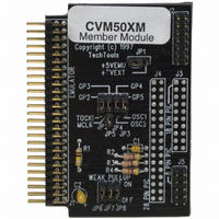
The CVM50XM Member module emulates the PIC12C508 and PIC12C509 micro-controllers.
These devices are part of the 12 bit PICmicro family and therefore requires the 5X FAMILY
module (CVM5XF) for operation.
EMULATOR DISCREPENCIES:
Due to BONDOUT limitations, the following features are either NOT SUPPORTED or are
modified slightly:
n The Wake-Up on pin change feature is not supported. The GPWU bit (OPTION.7) has no
n The “weak pull-up” resistors are enabled/disabled by hardware jumpers on the member pod
n Mathias provides the operating clock so the OSCCAL register has no affect. You can
n GP3 is an INPUT ONLY on the real device to accommodate that pin’s alternative use as
n In an actual device, setting the TOCS bit (OPTION.5) automatically forces GP2 to be an
n In an actual device, GPIO bits 6 and 7 are not implemented and will always read back ‘0’. In
JUMPER CONFIGURATIONS:
JP1: POWER
If the target permits, you can power the target from the emulator. To do so, place a jumper on JP1
between the center pin (+5EMU) and the pin marked +5VEXT. Moving the jumper the unmarked
position isolates the power rails. The default position is to ISOLATE the power rails.
affect. And the corresponding flag GPWUF (STATUS.7) has no meaning.
rather than through the GPPU bit (OPTION.6). This bit has no affect.
program Mathias for any clock frequency between 30KHz and 20MHz. The real PIC devices
run at around 4 MHz.
MCLR. The emulator provides a full INPUT/OUTPUT pin for this function. The MCLR
signal is brought into the bondout chip through a different connection. You should ALWAYS
SET the corresponding TRIS bit for GP3 to properly emulate this INPUT-ONLY behavior.
input, over-riding the TRIS bit for GP2. The emulator DOES NOT automatically force GP2
to be an input. YOU MUST SET TRIS.2 YOURSELF, if you use GP2 as a T0CS input.
the emulator, these bits are actually present and will read back whatever was last written to
them if the corresponding TRIS bits are cleared. If these TRIS bits are SET, then these bits
read FLOATING inputs and their value is indeterminate.
CVM50XM User’s Guide
PO Box 462101 Garland, TX 75046-2101
Voice: (972) 272-9392 FAX: (972) 494-5814
www.tech-tools.com sales@tech-tools.com
Related parts for CVM50XM
Image
Part Number
Description
Manufacturer
Datasheet
Request
R


Part Number:
Description:
MEMBER MODULE PIC16C773/774
Manufacturer:
TechTools
Datasheet:


CVM50XM Summary of contents
Page 1
... CVM50XM User’s Guide 9/25/97 The CVM50XM Member module emulates the PIC12C508 and PIC12C509 micro-controllers. These devices are part of the 12 bit PICmicro family and therefore requires the 5X FAMILY module (CVM5XF) for operation. EMULATOR DISCREPENCIES: Due to BONDOUT limitations, the following features are either NOT SUPPORTED or are modified slightly: n The Wake-Up on pin change feature is not supported ...
Page 2
JP2: Pin 5 function functions as GP2. (default) JP3*: Selects Pin 2 function functions as GP5. (default) JP4*: Select Pin 3 function functions as GP4. (default) * Since Mathias provides the clock for the bondout chip, JP3 and JP4 are ...