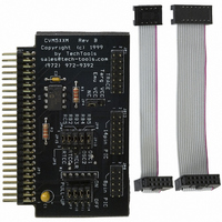
CVM5XXM TechTools, CVM5XXM Datasheet - Page 2

CVM5XXM
Manufacturer Part Number
CVM5XXM
Description
MEMBR MOD PIC12C50X/CE51X/16C505
Manufacturer
TechTools
Datasheet
1.CVM5XXM.pdf
(3 pages)
Specifications of CVM5XXM
Accessory Type
Member Module PIC12C50X/CE51X/16C505
For Use With/related Products
ClearView™/PRO MATE™ Mathias
JUMPER CONFIGURATIONS:
JP4: POWER
If the target permits, you can power the target from the emulator. To do so, place a jumper on
JP4 between the center pin (+5EMU) and the pin marked +5VEXT. Moving the jumper the
unmarked position isolates the power rails. The default position is to ISOLATE the power rails.
JP5 & JP15: Pin 5 function (both jumpers should be in the same position)
functions as GP2.
(default)
JP12*: Selects Pin 2 function
functions as GP5.
(default)
JP9*: Select Pin 3 function
functions as GP4.
(default)
* Since Mathias provides the clock for the bondout chip, JP12 and JP9 are usually set to the
GP position or removed completely. The no connection position is appropriate when your target
normally drives the OSC pins. This isolates the GP bits so that they are not in contention with
your target. NOTE: In either configuration, Mathias provides its own programmable clock,
making it easy to emulate a processor in either internal or external clock source mode.
No connection.*
No Connection*
functions as T0CKI


