28108 Parallax Inc, 28108 Datasheet - Page 3
28108
Manufacturer Part Number
28108
Description
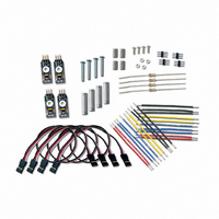
KIT QTI BOE-BOT LINE FOLLOWER
Manufacturer
Parallax Inc
Datasheet
1.28108.pdf
(6 pages)
Specifications of 28108
Accessory Type
QTI Infrared
Product
Microcontroller Accessories
Lead Free Status / RoHS Status
Lead free / RoHS Compliant
For Use With/related Products
Boe-Bot®
Lead Free Status / Rohs Status
Lead free / RoHS Compliant


Building the Sensing Circuits
Each QTI B pin is tied to Vss (ground) and each W pin is connected to Vdd (5 V). R pin connects to a
BASIC Stamp I/O pin:
Copyright © Parallax Inc.
4. Attach a QTI sensor to the other end of each threaded standoff, using a 3/8-inch screw. The
5. If necessary, slightly loosen the 7/8-inch screws and adjust the position of the QTI sensors so
6. Tighten all connections securely.
√
sensors should be facing downwards, and the 3-pin headers on each sensor should be pointing
towards the back of the chassis.
that they are closely positioned edge to edge.
Far right to P4
Mid right to P5
Use the schematic and the wiring diagram below to build the circuits for the three-pin headers.
Although there are many ways this circuit can be built, the setup shown below is useful because
it's thrifty with breadboard real-estate. Also, if you are using a HomeWork Board with your Boe-
Bot, it won’t interfere with the servo connections.
QTI LIne Follower AppKit (#28108)
Mid left to P6
Mid right to P7
v2.0 3/23/2009 Page 3 of 6
.
Related parts for 28108
Image
Part Number
Description
Manufacturer
Datasheet
Request
R


Part Number:
Description:
Microcontroller Modules & Accessories DISCONTINUED BY PARALLAX
Manufacturer:
Parallax Inc

Part Number:
Description:
BOOK UNDERSTANDING SIGNALS
Manufacturer:
Parallax Inc
Datasheet:


Part Number:
Description:
COMPETITION RING FOR SUMOBOT
Manufacturer:
Parallax Inc
Datasheet:


Part Number:
Description:
TEXT INFRARED REMOTE FOR BOE-BOT
Manufacturer:
Parallax Inc
Datasheet:
Part Number:
Description:
BOARD EXPERIMENT+LCD NX-1000
Manufacturer:
Parallax Inc
Datasheet:

Part Number:
Description:
CONTROLLER 16SERVO MOTOR CONTROL
Manufacturer:
Parallax Inc
Datasheet:

Part Number:
Description:
BASIC STAMP LOGIC ANALYZER
Manufacturer:
Parallax Inc
Datasheet:

Part Number:
Description:
IC MCU 2K FLASH 50MHZ SO-18
Manufacturer:
Parallax Inc
Datasheet: