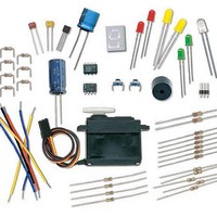
28122 Parallax Inc, 28122 Datasheet - Page 273

28122
Manufacturer Part Number
28122
Description
KIT WHAT'S A MICRO:PARTS ONLY
Manufacturer
Parallax Inc
Datasheet
1.28123.pdf
(340 pages)
Specifications of 28122
Accessory Type
Parts Kit
Product
Microcontroller Accessories
Core Processor
PIC16C57c
Flash
128 Bytes
Operating Supply Voltage
9 V
Board Size
31 mm x 16 mm
For Use With/related Products
Board of Education Full Kit
Lead Free Status / RoHS Status
Lead free / RoHS Compliant
- Current page: 273 of 340
- Download datasheet (6Mb)
10 kΩ
(1) Potentiometer – 10 kΩ
(3) Jumper wires
Building and Testing the Transistor Circuit
Figure 9-3 shows a circuit that you can use to manually control how much current the
transistor allows through the LED. By twisting the knob on the potentiometer, the circuit
will deliver different amounts of current to the transistor’s base. This will cause a change
in the amount of current the transistor allows to pass from its collector to its emitter. The
LED will give you a clear indication of the change by glowing more or less brightly.
Your Turn – Switching the Transistor On/Off
If all you want to do is switch a transistor on and off, you can use the circuit shown in
Figure 9-4. When the BASIC Stamp sends a high signal to this circuit, it will make it so
that the transistor conducts as much current as if you adjusted the potentiometer for
maximum brightness. When the BASIC Stamp sends a low signal to this circuit, it will
cause the transistor to stop conducting current, and the LED should emit no light.
POT
Vdd
Vss
√
√
Build the circuit shown in Figure 9-3.
Turn the knob on the potentiometer and verify that the LED changes
brightness in response to a change in the position of the potentiometer’s wiper
terminal.
100
100
kΩ
kΩ
Vdd
Vss
LED
P15
P14
P13
P12
P11
P10
P9
P8
P7
P6
P5
P4
P3
P2
P1
P0
X2
X3
Vdd
Vin
Vss
Figure 9-3
Manual
Potentiometer
Controlled
Transistor
Circuit
Related parts for 28122
Image
Part Number
Description
Manufacturer
Datasheet
Request
R

Part Number:
Description:
Microcontroller Modules & Accessories DISCONTINUED BY PARALLAX
Manufacturer:
Parallax Inc

Part Number:
Description:
BOOK UNDERSTANDING SIGNALS
Manufacturer:
Parallax Inc
Datasheet:

Part Number:
Description:
COMPETITION RING FOR SUMOBOT
Manufacturer:
Parallax Inc
Datasheet:

Part Number:
Description:
TEXT INFRARED REMOTE FOR BOE-BOT
Manufacturer:
Parallax Inc
Datasheet:

Part Number:
Description:
BOARD EXPERIMENT+LCD NX-1000
Manufacturer:
Parallax Inc
Datasheet:

Part Number:
Description:
CONTROLLER 16SERVO MOTOR CONTROL
Manufacturer:
Parallax Inc
Datasheet:

Part Number:
Description:
BASIC STAMP LOGIC ANALYZER
Manufacturer:
Parallax Inc
Datasheet:

Part Number:
Description:
IC MCU 2K FLASH 50MHZ SO-18
Manufacturer:
Parallax Inc
Datasheet:


