PKSERIAL-I2C1 Microchip Technology, PKSERIAL-I2C1 Datasheet
PKSERIAL-I2C1
Specifications of PKSERIAL-I2C1
Available stocks


Related parts for PKSERIAL-I2C1


PKSERIAL-I2C1 Summary of contents
Page 1
... Microchip Technology Inc. PICkit™ Serial I Demo Board User’s Guide 2 C™ DS51657A ...
Page 2
... Select Mode, Smart Serial, SmartTel, Total Endurance, UNI/O, WiperLock and ZENA are trademarks of Microchip Technology Incorporated in the U.S.A. and other countries. SQTP is a service mark of Microchip Technology Incorporated in the U.S.A. All other trademarks mentioned herein are property of their respective companies. ...
Page 3
... A.3 Board - Top Silk Layer ................................................................................. 11 A.4 Board - Top Layer ........................................................................................ 11 A.5 Board - Bottom Layer ................................................................................... 11 Appendix B. Bill Of Materials (BOM) .......................................................................... 13 Worldwide Sales and Service .................................................................................... 14 © 2007 Microchip Technology Inc. PICkit™ SERIAL I BOARD USER’S GUIDE Table of Contents 2 C™ Demo Board Kit Includes ............................. 6 2 C™ ...
Page 4
... PICkit™ Serial I C™ Demo Board User’s Guide NOTES: DS51657A-page iv © 2007 Microchip Technology Inc. ...
Page 5
... Appendix A. “Schematic and Layouts” – Shows the schematic and layout diagrams for the PICkit™ Serial I • Appendix B. “Bill Of Materials (BOM)” – Lists the parts used to build the PICkit™ Serial I © 2007 Microchip Technology Inc. PICkit™ SERIAL I BOARD USER’S GUIDE Preface ...
Page 6
... Optional arguments mcc18 [options] file [options] Choice of mutually exclusive errorlevel {0|1} arguments selection Replaces repeated text var_name [, var_name...] Represents code supplied by void main (void) user { ... } © 2007 Microchip Technology Inc. Examples ® IDE User’s Guide ...
Page 7
... Customers should contact their distributor, representative or field application engineer for support. Local sales offices are also available to help customers. A listing of sales offices and locations is included in the back of this document. Technical support is available through the web site at: http://support.microchip.com © 2007 Microchip Technology Inc. 2 C™ Demo Board. Other useful 2 C Serial EEPROM" ...
Page 8
... PICkit™ Serial I C™ Demo Board User’s Guide DOCUMENT REVISION HISTORY Revision A (May 2007) • Initial Release of this Document. DS51657A-page 4 © 2007 Microchip Technology Inc. ...
Page 9
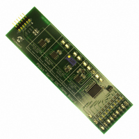
... Figure 1-1 shows the Rev. 1 board with an ECO (Engineering Change Notice) applied to it. The Rev. 1 board with ECO and the Rev. 2 board are electrically the same. Refer to Appendix A. “Schematic and Layouts” for Rev. 2 schematics and board layouts. © 2007 Microchip Technology Inc. PICkit™ SERIAL I BOARD USER’S GUIDE 2 C™ ...
Page 10
... C Master Communications tutorial is available on the Microchip Technology website. Click on the links: Support --> Getting Started --> PIC MCU Tutorials --> Master Mode • Several application notes are available on the Microchip Technology website. Click on links: Design --> App Notes --> Function: Communications --> I 1.4 WHAT THE PICkit™ SERIAL I This PICkit™ Serial I • ...
Page 11
... Connector P1 pin assignments are listed in Table 2-1. TABLE 2-1: Pin © 2007 Microchip Technology Inc. PICkit™ SERIAL I BOARD USER’S GUIDE 2 C™ Demo Board was designed to easily connect to the PICkit 2 C Master Communications mode for configuration and 2 C master mode serial communications and 2 C™ ...
Page 12
... The output of the MCP23008 is connected to test points GP0 through GP7 and GND. These test points can be monitored by a volt meter or connected to an external device. LEDs DS1 through DS8 can be used to monitor the output by closing JP1 with a 2-pin shunt or disable by removing JP1. DS51657A-page 8 ) will be between 0 - 2.5V. SW and IN , OUT © 2007 Microchip Technology Inc. ...
Page 13
... C™ Demo Board User’s Guide: • Board – Schematic • Board – Top Silk Layer • Board – Top Metal Layer • Board – Bottom Metal Layer © 2007 Microchip Technology Inc. 2 PICkit™ SERIAL I BOARD USER’S GUIDE C™ DEMO ...
Page 14
... PICkit™ Serial I C™ Demo Board User’s Guide A.2 BOARD - SCHEMATIC DS51657A-page 10 © 2007 Microchip Technology Inc. ...
Page 15
... A.3 BOARD - TOP SILK LAYER A.4 BOARD - TOP LAYER A.5 BOARD - BOTTOM LAYER © 2007 Microchip Technology Inc. DS51657A-page 11 ...
Page 16
... PICkit™ Serial I C™ Demo Board User’s Guide NOTES: DS51657A-page 12 © 2007 Microchip Technology Inc. ...
Page 17
... U4 10-Bit Digital-to-Analog Converter with Two-Wire Interface 1 U5 8-Bit I/O Expander with Serial Interface Microchip Technology 1 U6 MCP1525, 2.5V Voltage Reference Note 1: The components listed in this Bill of Materials are representative of the PCB assembly. The released BOM used in manufacturing uses all RoHS-compliant components. ...
Page 18
... Fax: 886-3-572-6459 Taiwan - Kaohsiung Tel: 886-7-536-4818 Fax: 886-7-536-4803 Taiwan - Taipei Tel: 886-2-2500-6610 Fax: 886-2-2508-0102 Thailand - Bangkok Tel: 66-2-694-1351 Fax: 66-2-694-1350 © 2007 Microchip Technology Inc. EUROPE Austria - Wels Tel: 43-7242-2244-39 Fax: 43-7242-2244-393 Denmark - Copenhagen Tel: 45-4450-2828 Fax: 45-4485-2829 France - Paris Tel: 33-1-69-53-63-20 ...