AC164120 Microchip Technology, AC164120 Datasheet - Page 15
AC164120
Manufacturer Part Number
AC164120
Description
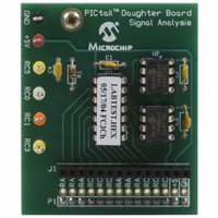
BOARD SIGNAL ANALYSIS PICKIT
Manufacturer
Microchip Technology
Series
PICtail™r
Specifications of AC164120
Main Purpose
Interface, Signal Analysis
Embedded
Yes, MCU, 8-Bit
Utilized Ic / Part
PICkit™ PICtail™1
Primary Attributes
Real-time Strip Chart, Oscilloscope, Fast Fourier Transformation (FFT)
Secondary Attributes
Histogram
Silicon Manufacturer
Microchip
Core Architecture
PIC
Core Sub-architecture
PIC16
Features
Real-Time Strip Chart, Fast Fourier Transformation
Silicon Core Number
PIC16F
Silicon Family Name
PIC16F6xxx
Rohs Compliant
Yes
Lead Free Status / RoHS Status
Lead free / RoHS Compliant
For Use With
PICkit Flash Starter Kit
Lead Free Status / RoHS Status
Lead free / RoHS Compliant, Lead free / RoHS Compliant
Available stocks
Company
Part Number
Manufacturer
Quantity
Price
Company:

Part Number:
AC164120
Manufacturer:
Microchip Technology
Quantity:
135


2004 Microchip Technology Inc.
1.5.2
Real-time mode refers to the Signal Analysis Application mode that commands the
PIC16F684 to perform one analog-to-digital (A/D) conversion from RC0/AN4 I/O port
pin. The 10-bit conversion data is immediately sent to the PIC16C745 for transfer to the
PC USB port. The Signal Analysis Application then displays the data in a real-time strip
chart format.
1.5.3
Acquisition mode refers to the Signal Analysis Application mode that commands the
PIC16F684 to perform a specified number of A/D conversions at a specified speed
(samples per second) and store the results in the serial EEPROMs.
The acquisition process is controlled by Timer0. The configuration command looks up
precalculated Timer0 prescaler and Timer0 values. This ensures Timer0 will generate
an interrupt on time as specified by the speed configuration parameter. When Timer0
overflows, the interrupt is triggered and initiates an analog-to-digital conversion and
restarts Timer0.
Writing to a serial EEPROM consists of writing to a page of memory (32 bytes for the
25LC640) and initiating a Write cycle. A write cycle can take a maximum of 5 ms (3 ms
typical) to complete. Thus, in order to store A/D conversions at high speeds, two serial
EEPROMs are used. The data conversions are stored in the two serial EEPROMS by
alternating (interleaving) between the two devices.
Figure 1-4 graphically illustrates the Acquisition mode data flow.
FIGURE 1-4:
Note: The Signal Analysis PICtail Daughter Board is designed as a development
ADC
•The Analog-to-Digital Converter is referenced to V
•Timing of the samples (in Acquisition mode) is controlled by Timer0 and
Real-time Mode
Acquisition Mode
tool rather than laboratory quality equipment. To reduce product costs, a
number of design choices have been made in favor of lower cost over
increased accuracy. These choices may affect the accuracy and
repeatability of measurements. These potential sources of error include:
by the USB cable. The PICkit 1 Signal Analysis PC Application
assumes its 5.00V, however, the USB specifies only 4.75-5.25V.
the internal oscillator on the PICmicro device. Check the
PIC16C745/765 8-Bit CMOS Microcontroller with the USB data sheet
(DS41124), for actual specifications on oscillator tolerances.
Signal Analysis PICtail™ Daughter Board
PICA2DLAB ACQUISITION MODE DATA FLOW DIAGRAM
Queuing
Function
(ISR)
Circular Queue
(Acquisition)
Dequeuing
Function
DD
, which is supplied
(2x25LC640)
EEPROM
EERead
Synchronous
DS51476A-page 11
Serial
Related parts for AC164120
Image
Part Number
Description
Manufacturer
Datasheet
Request
R

Part Number:
Description:
Manufacturer:
Microchip Technology Inc.
Datasheet:
Part Number:
Description:
Manufacturer:
Microchip Technology Inc.
Datasheet:
Part Number:
Description:
Manufacturer:
Microchip Technology Inc.
Datasheet:
Part Number:
Description:
Manufacturer:
Microchip Technology Inc.
Datasheet:
Part Number:
Description:
Manufacturer:
Microchip Technology Inc.
Datasheet:
Part Number:
Description:
Manufacturer:
Microchip Technology Inc.
Datasheet:
Part Number:
Description:
Manufacturer:
Microchip Technology Inc.
Datasheet:
Part Number:
Description:
Manufacturer:
Microchip Technology Inc.
Datasheet: