ATDVK90CAN1 Atmel, ATDVK90CAN1 Datasheet - Page 40
ATDVK90CAN1
Manufacturer Part Number
ATDVK90CAN1
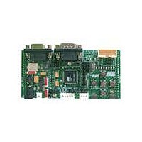
Description
KIT DEV FOR AT90CAN128 MCU
Manufacturer
Atmel
Specifications of ATDVK90CAN1
Main Purpose
*
Embedded
*
Utilized Ic / Part
AT90CAN AVR Devices
Primary Attributes
*
Secondary Attributes
*
Processor To Be Evaluated
AT90CAN
Data Bus Width
8 bit
Interface Type
RS-232, SPI, TWI
Core Architecture
AVR
Core Sub-architecture
AVR UC3
Kit Contents
Board, AT90CAN128 Sample Microcontroller, 9V Battery Power Cable, CD-ROM, Manuals
Features
RS232, CAN, LIN, SPI & TWI Serial Interface
Rohs Compliant
Yes
Lead Free Status / RoHS Status
Contains lead / RoHS non-compliant
Available stocks
Company
Part Number
Manufacturer
Quantity
Price
Company:

Part Number:
ATDVK90CAN1
Manufacturer:
Atmel
Quantity:
135


4381A–AVR–Sept 04
Using the DVK90CAN1
3.11
3.12
3.12.1
page 38
Test Points
Configuration Pads
Configuration Pads Listing
Excepted for T1, all the test points are free of connection. These tests points are
referred in the micro controller sheet of schematics.
There are 7 test points implemented close to AT90CAN128 micro-controller:
1. (T1) GND - Board reference voltage
2. (T6) AREF - Pin Analog Reference of AT90CAN128
3. (T4) VCC - Board and AT90CAN128 Power Supply
4. (T2) AVCC - Pin Analog Power Supply of AT90CAN128
5. (T7) TA0 (no signal)
6. (T8) VPP (no signal, PG.2 signal only)
7. (T10) CLKO - Pin PortC.7/Clock Output of AT90CAN128
Figure 3-47 . AT90CAN128 Test Points
All configuration pads are located on the bottom side of the board. They are used to
disconnect/connect on-board peripherals or elements.
The default configuration is: connect.
Datasheet, sections “I/O Ports” and “Memory Programming”)
T2 = AVCC
T6 = AREF
T8 = VPP
T7 = TA0
DVK90CAN1 Hardware User Guide
T10 = CLKO
(c.f. AT90CAN128
Related parts for ATDVK90CAN1
Image
Part Number
Description
Manufacturer
Datasheet
Request
R

Part Number:
Description:
DEV KIT FOR AVR/AVR32
Manufacturer:
Atmel
Datasheet:

Part Number:
Description:
INTERVAL AND WIPE/WASH WIPER CONTROL IC WITH DELAY
Manufacturer:
ATMEL Corporation
Datasheet:
Part Number:
Description:
Low-Voltage Voice-Switched IC for Hands-Free Operation
Manufacturer:
ATMEL Corporation
Datasheet:
Part Number:
Description:
MONOLITHIC INTEGRATED FEATUREPHONE CIRCUIT
Manufacturer:
ATMEL Corporation
Datasheet:
Part Number:
Description:
AM-FM Receiver IC U4255BM-M
Manufacturer:
ATMEL Corporation
Datasheet:
Part Number:
Description:
Monolithic Integrated Feature Phone Circuit
Manufacturer:
ATMEL Corporation
Datasheet:
Part Number:
Description:
Multistandard Video-IF and Quasi Parallel Sound Processing
Manufacturer:
ATMEL Corporation
Datasheet:
Part Number:
Description:
High-performance EE PLD
Manufacturer:
ATMEL Corporation
Datasheet:
Part Number:
Description:
8-bit Flash Microcontroller
Manufacturer:
ATMEL Corporation
Datasheet:
Part Number:
Description:
2-Wire Serial EEPROM
Manufacturer:
ATMEL Corporation
Datasheet: