ATDVK90CAN1 Atmel, ATDVK90CAN1 Datasheet - Page 41
ATDVK90CAN1
Manufacturer Part Number
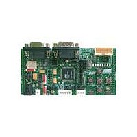
ATDVK90CAN1
Description
KIT DEV FOR AT90CAN128 MCU
Manufacturer
Atmel
Specifications of ATDVK90CAN1
Main Purpose
*
Embedded
*
Utilized Ic / Part
AT90CAN AVR Devices
Primary Attributes
*
Secondary Attributes
*
Processor To Be Evaluated
AT90CAN
Data Bus Width
8 bit
Interface Type
RS-232, SPI, TWI
Core Architecture
AVR
Core Sub-architecture
AVR UC3
Kit Contents
Board, AT90CAN128 Sample Microcontroller, 9V Battery Power Cable, CD-ROM, Manuals
Features
RS232, CAN, LIN, SPI & TWI Serial Interface
Rohs Compliant
Yes
Lead Free Status / RoHS Status
Contains lead / RoHS non-compliant
Available stocks
Company
Part Number
Manufacturer
Quantity
Price
Company:

Part Number:
ATDVK90CAN1
Manufacturer:
Atmel
Quantity:
135


4381B–AVR–07/08
Using the DVK90CAN1
3.11
3.12
3-40
Test Points
Configuration Pads
Excepted for T1, all the test points are free of connection. These tests points are
referred in the micro controller sheet of schematics.
There are 7 test points implemented close to AT90CAN128 micro-controller:
1. (T1) GND - Board reference voltage
2. (T6) AREF - Pin Analog Reference of AT90CAN128
3. (T4) VCC - Board and AT90CAN128 Power Supply
4. (T2) AVCC - Pin Analog Power Supply of AT90CAN128
5. (T7) TA0 (no signal)
6. (T8) VPP (no signal, PG.2 signal only)
7. (T10) CLKO - Pin PortC.7/Clock Output of AT90CAN128
Figure 3-47 . AT90CAN128 Test Points
All configuration pads are located on the bottom side of the board. They are used to
disconnect/connect on-board peripherals or elements.
The default configuration is: connect.
Datasheet, sections “I/O Ports” and “Memory Programming”)
T2 = AVCC
T6 = AREF
T8 = VPP
T7 = TA0
DVK90CAN1 Hardware User Guide
T10 = CLKO
(c.f.
AT90CAN128
Related parts for ATDVK90CAN1
Image
Part Number
Description
Manufacturer
Datasheet
Request
R

Part Number:
Description:
DEV KIT FOR AVR/AVR32
Manufacturer:
Atmel
Datasheet:

Part Number:
Description:
INTERVAL AND WIPE/WASH WIPER CONTROL IC WITH DELAY
Manufacturer:
ATMEL Corporation
Datasheet:
Part Number:
Description:
Low-Voltage Voice-Switched IC for Hands-Free Operation
Manufacturer:
ATMEL Corporation
Datasheet:
Part Number:
Description:
MONOLITHIC INTEGRATED FEATUREPHONE CIRCUIT
Manufacturer:
ATMEL Corporation
Datasheet:
Part Number:
Description:
AM-FM Receiver IC U4255BM-M
Manufacturer:
ATMEL Corporation
Datasheet:
Part Number:
Description:
Monolithic Integrated Feature Phone Circuit
Manufacturer:
ATMEL Corporation
Datasheet:
Part Number:
Description:
Multistandard Video-IF and Quasi Parallel Sound Processing
Manufacturer:
ATMEL Corporation
Datasheet:
Part Number:
Description:
High-performance EE PLD
Manufacturer:
ATMEL Corporation
Datasheet:
Part Number:
Description:
8-bit Flash Microcontroller
Manufacturer:
ATMEL Corporation
Datasheet:
Part Number:
Description:
2-Wire Serial EEPROM
Manufacturer:
ATMEL Corporation
Datasheet: