DM330021 Microchip Technology, DM330021 Datasheet - Page 15
DM330021
Manufacturer Part Number
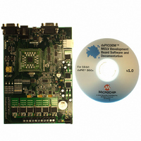
DM330021
Description
KIT DEMO DSPIC33 MCLV
Manufacturer
Microchip Technology
Series
dsPIC™r
Datasheet
1.DM330021.pdf
(40 pages)
Specifications of DM330021
Main Purpose
Power Management, Motor Control
Embedded
Yes, MCU, 16-Bit
Utilized Ic / Part
dsPIC33F
Primary Attributes
3-Ph BLDC or PMSM, 48V, 15A
Secondary Attributes
CAN, LIN, USB, RS-232 Interfaces
Processor To Be Evaluated
dsPIC33F
Interface Type
RS-232, USB
Lead Free Status / RoHS Status
Lead free / RoHS Compliant
Lead Free Status / RoHS Status
Lead free / RoHS Compliant, Lead free / RoHS Compliant
Available stocks
Company
Part Number
Manufacturer
Quantity
Price
Company:

Part Number:
DM330021
Manufacturer:
Microchip Technology
Quantity:
135
Company:
Part Number:
DM330021-2
Manufacturer:
MICROCHIP
Quantity:
12 000


2.1
© 2008 Microchip Technology Inc.
PIM CONFIGURATION
This chapter describes the hardware components of the dsPICDEM MCLV
Development Board. Topics covered include:
• PIM Configuration
• Board Connectors
• User Interface Hardware
A +24V power supply connected to the Power Connector terminal (J2) or Auxiliary
Power Tab Fast-On Connector terminals (BP1-BP2) supplies power to the control
circuits and DC bus of the board. It is recommended that you use a 24V power supply
listed as an accessory (Part Number AC002013) on the Microchip web site
(www.microchip.com).
The various components on the board receive the power as follows:
• The Gate drivers receive +15V power from a 15V regulator.
• The CAN driver receives +5V power from a 5V regulator.
• The LIN driver receives V
• A dsPIC33F motor control device receives +3.3V power from a +3.3V regulator.
• The RS-232 UART interface receives +3.3V power from a +3.3V regulator.
• The PIC18LF2450 USB to UART Bridge receives +3.3V power from a +3.3V
This section summarizes the resistor configuration required to connect the PIM pins to
dsPIC DSC pins. The following PIMs can be configured on the dsPICDEM MCLV
Development Board:
• dsPIC33FJ256MC710 PIM (MA330013)
• dsPIC33FJ12MC202 PIM (MA330014)
• dsPIC33FJ32MC204 PIM (MA330017)
• dsPIC33FJ128MC804 PIM (MA330018)
The tables that follow describe the PIM configuration details.
regulator.
Note 1:
Note:
Chapter 2. Hardware Overview
2:
When using PIMs, make sure that the 28-pin SOIC dsPIC DSC is removed
from the dsPICDEM MCLV Development Board.
a) Connect the power supply to jumper J7, and keep jumper J6 open.
b) Power the circuit components, MCU, and the gate drivers using a
If the input voltage value is less than 16V, remove the 15V voltage
regulator and short jumper J3.
To use a higher DC voltage bus (24V-48V), complete the following steps:
separate 16V-24V power supply connected to the power connector
J2 or BP1-BP2.
BAT
power from the LIN connector J1.
DEVELOPMENT BOARD
dsPICDEM
USER’S GUIDE
TM
DS70331A-page 11
MCLV
Related parts for DM330021
Image
Part Number
Description
Manufacturer
Datasheet
Request
R

Part Number:
Description:
Manufacturer:
Microchip Technology Inc.
Datasheet:
Part Number:
Description:
Manufacturer:
Microchip Technology Inc.
Datasheet:
Part Number:
Description:
Manufacturer:
Microchip Technology Inc.
Datasheet:
Part Number:
Description:
Manufacturer:
Microchip Technology Inc.
Datasheet:
Part Number:
Description:
Manufacturer:
Microchip Technology Inc.
Datasheet:
Part Number:
Description:
Manufacturer:
Microchip Technology Inc.
Datasheet:
Part Number:
Description:
Manufacturer:
Microchip Technology Inc.
Datasheet:
Part Number:
Description:
Manufacturer:
Microchip Technology Inc.
Datasheet: