DV250501 Microchip Technology, DV250501 Datasheet - Page 17
DV250501
Manufacturer Part Number
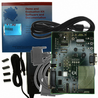
DV250501
Description
KIT DEV CAN MCP250XX
Manufacturer
Microchip Technology
Type
Network Controller & Processorr
Specifications of DV250501
Main Purpose
Interface, CAN I/O Expander
Embedded
Yes, MCU, 8-Bit
Utilized Ic / Part
MCP25020, MCP25050
Primary Attributes
V2.0B up to 1Mb/s Data Rate
Data Rate
1 Mbps
Interface Type
CAN
Operating Voltage
2.7 V to 5.5 V
Product
Modules
Lead Free Status / RoHS Status
Lead free / RoHS Compliant
Secondary Attributes
-
Lead Free Status / Rohs Status
Lead free / RoHS Compliant
Other names
Q1221418
Available stocks
Company
Part Number
Manufacturer
Quantity
Price
Company:

Part Number:
DV250501
Manufacturer:
MICROCHIP
Quantity:
12 000
Part Number:
DV250501
Manufacturer:
MICROCHIP/微芯
Quantity:
20 000


M
2.1
2.2
2.3
2004 Microchip Technology Inc.
INTRODUCTION
HIGHLIGHTS
SETTING UP THE BASIC TEMPLATE EVALUATION MODE
Chapter 2. MCP250XX Basic View Tutorial
This tutorial discusses the evaluation portion of the kit, details the demonstration soft-
ware (Basic template), CAN system (PC Node and Node B) and covers the steps
required to successfully run the demonstration network.
The user defaults for Node B are preprogrammed at the factory. Therefore, no user
default programming is necessary. No discussion of programming user defaults will
take place in this chapter, as this is detailed in Chapter 4. “Programming the
MCP250XX User Defaults”.
This chapter covers the following topics:
• Setting up Evaluation mode
• Establishing communications
• Explaining the CAN messages
The MCP250XX Development Kit’s “Basic” template contains the following major
elements:
1. Menu Bar (Figure 2-1) – The layout is typical of most Windows menu bars.
2. PC Node Bit Timing and Mode (Figure 2-2) – The bit timing and the mode of
3. Board Status (Figure 2-3) – Indicates if the board is connected to the PC and
4. Message Format Window (Figure 2-4) – Selects how CAN messages are
5. Bus Monitor Window (Figure 2-5) – Also known as the “Output” window. This
6. MCP250XX Demonstration (Figure 2-6) – This window is the graphical
FIGURE 2-1:
Note:
operation (Normal and Configuration) for the MCP2515 (PC Node) are
configured with this window.
also indicates the parallel port address used.
formatted and interpreted. The default is “Standard Text Format” and is used for
the demonstration program. The other format is used with the CAN Kingdom
higher layer protocol.
window shows all bus traffic.
interpretation of Node B (the demonstration node).
The software must be installed and the hardware connected to run the
demonstration program.
MENU BAR
MCP250XX USER’S GUIDE
DS51266C-page 13
Related parts for DV250501
Image
Part Number
Description
Manufacturer
Datasheet
Request
R

Part Number:
Description:
Manufacturer:
Microchip Technology Inc.
Datasheet:
Part Number:
Description:
Manufacturer:
Microchip Technology Inc.
Datasheet:
Part Number:
Description:
Manufacturer:
Microchip Technology Inc.
Datasheet:
Part Number:
Description:
Manufacturer:
Microchip Technology Inc.
Datasheet:
Part Number:
Description:
Manufacturer:
Microchip Technology Inc.
Datasheet:
Part Number:
Description:
Manufacturer:
Microchip Technology Inc.
Datasheet:
Part Number:
Description:
Manufacturer:
Microchip Technology Inc.
Datasheet:
Part Number:
Description:
Manufacturer:
Microchip Technology Inc.
Datasheet: