CDK2000-LCO Cirrus Logic Inc, CDK2000-LCO Datasheet
CDK2000-LCO
Specifications of CDK2000-LCO


Related parts for CDK2000-LCO


CDK2000-LCO Summary of contents
Page 1
... CS2000 clocking device family, including all members of the CS2000, CS2100, CS2200, and CS2300 device sub-families. For one-time programmable (OTP) parts, the CDK2000 platform also allows for the development, test, and production programming of custom device configurations. The on-board firmware handles all aspects of program- ming the DUT and transitioning it between modes ...
Page 2
... Development and Production Modes .................................................................................... 13 4.4.3 Program Sequence Execution and Result Codes ................................................................. 14 4.4.4 Result Code Details ............................................................................................................... 15 5. USER INTERFACE ELEMENTS OVERVIEW ...................................................................................... 16 6. CDB2000-MB SCHEMATICS AND LAYOUT ...................................................................................... 17 7. CDB2000-DC SCHEMATICS AND LAYOUT ....................................................................................... 22 8. CDB2000-PC SCHEMATICS AND LAYOUT ....................................................................................... 24 9. ORDERING INFORMATION ................................................................................................................ 26 10. REVISION HISTORY .......................................................................................................................... 26 2 CDK2000 DS821DB1 ...
Page 3
... Figure 20.CDB2000-PC Top Layer ........................................................................................................... 25 Figure 21.CDB2000-PC Inner Layer 1 - Ground ....................................................................................... 25 Figure 22.CDB2000-PC Inner Layer 2 - Power ......................................................................................... 25 Figure 23.CDB2000-PC Bottom Layer ...................................................................................................... 25 LIST OF TABLES Table 1. CDB2000-PC Family Daughter Cards .......................................................................................... 4 Table 2. CDB2000-DC Family Daughter Cards .......................................................................................... 4 Table 3. Error Codes ................................................................................................................................. 14 Table 4. User Interface Elements .............................................................................................................. 16 Table 5. Dip Switch Positions .................................................................................................................... 16 DS821DB1 CDK2000 3 ...
Page 4
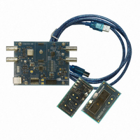
... DEVELOPMENT PLATFORM OVERVIEW 1.1 Hardware Components The CDK2000 clocking device development platform hardware components consist of a motherboard and a number of individual daughter cards that, when connected, make a complete development system. The CDB2000-MB is the motherboard of the development system. This board houses all clock I/O connec- tors, control switches, power supplies, and PC interface hardware ...
Page 5
... The Wizard will start up in demonstration (Demo) mode regardless of the presence of USB connection to a CDK2000 (Noted by the text “CS2000 Wizard is running in DEMO Mode” in the bottom left and “DISCON- NECTED” in the menu bar). In Demo mode the different devices in the CS2000 family may be selected from the ‘ ...
Page 6
... The M2 Low/High button simulates the usage of the M2 pin. The bright red drop down selects the M2 global config parameter and the associated control will be outlined in red. A screen capture of the Configuration Wizard configured for -OTP is shown below. Figure 3. CS2000 Family Configuration Wizard, CS2000-OTP Device Selected in Demo Mode 6 Figure 2. Calculator Tool CDK2000 DS821DB1 ...
Page 7
... CS2x00-OTP family datasheet. This also allows the view of all 4 modal configuration sets at once for quicker setup and for verification of settings. A screen capture of the Configuration Wizard configured for -OTP is shown below. Figure 4. CS2000 Family Configuration Wizard, CS2000-OTP Device Selected in Form Entry Mode DS821DB1 CDK2000 7 ...
Page 8
... Click “Yes” to allow the GUI to configure itself according to the device found on the CDK2000. If this is not the device you intended to evaluate then click “No” which powers down the device and you may then change the daughter card to the appropriate device. ...
Page 9
... Device mismatch!” message. Click “Yes” to allow the GUI to configure itself according to the device on the CDK2000. If this is not the device you intended to evaluate then click “No” which powers down the device and you may then change the daughter card to the appropriate device. ...
Page 10
... Power Supply The entire CDK2000 platform is powered via the USB connector from a self-powered USB hub, which pro- vides a voltage between 4.75 and 5.25 V. Other USB compliant power supplies, such (wall) adapt (car) adapter, may be used as well. Whenever a suitable USB power supply is connected, D13 will be lit to indicate such ...
Page 11
... Micro-Controller The CDB2000-MB utilizes a SiLabs ® 8051-compatible micro-controller with integrated USB PHY for con- venient interconnect to a PC. The micro-controller comes pre-programmed with custom firmware that allows it to interact with the CDK2000 Configuration Wizard as well as operate in Stand-Alone mode without a PC. DS821DB1 Table 1 ...
Page 12
... Power Supply A USB connection is required to power the CDK2000 platform and the DUT. If the board used in software mode, it must be connected to a PC, either directly or via a self-powered hub. If board operation in software mode is not required, an alternate USB power supply (such as a wall adapter) may be used instead ...
Page 13
... DUTs may be pro- grammed with this configuration therefore possible to develop and test the configuration file on a PC, and then transfer the CDK2000 platform into a production environment to program a large quantity of de- vices without requiring a PC. ...
Page 14
... If the green SUCC LED is lit solid, the programming sequence concluded without errors. The other two status LEDs indicate warnings, if any. 14 Section 4.1.3 on page 13 Table 3 below. Result/Status Programming in progress Invalid: no DUT found Error: register read error Table 3. Error Codes CDK2000 for details). D5 (PROG.RUN) will be lit D5 (RUN) D6 (SUCC) D7 (FAIL) ON OFF OFF OFF ON OFF OFF ON ...
Page 15
... DUT is present, or the DUT is defective. Replace the DUT before proceeding. • 7 (Invalid: DUT is not a CS2000 family device DUT was found on the board, but it doesn’t appear CS2000 family device. The CDK2000 platform only supports CS2000 family devices. Replace the DUT before proceeding. ...
Page 16
... M0 on DUT driven logic ‘low’ DUT driven logic ‘low’ DUT driven logic ‘low’ Production mode active Standard operation Table 5. Dip Switch Positions CDK2000 Table 5 outlines the various DIP switch Section 4.4.3 on page 14 for details) Section 4.4.3 on page 14 for details) Section 4 ...
Page 17
CDB2000-MB SCHEMATICS AND LAYOUT Figure 5. CDB2000-MB Schematic Page 1 ...
Page 18
Figure 6. CDB2000-MB Schematic Page 2 ...
Page 19
... DS821DB1 Figure 7. CDB2000-MB Component Map Figure 8. CDB2000-MB Top Layer CDK2000 19 ...
Page 20
... Figure 9. CDB2000-MB Inner Layer 1 - Ground Figure 10. CDB2000-MB Inner Layer 2 - Power 20 CDK2000 DS821DB1 ...
Page 21
... DS821DB1 Figure 11. CDB2000-MB Bottom Layer CDK2000 21 ...
Page 22
... CDB2000-DC SCHEMATICS AND LAYOUT 22 Figure 12. CDB2000-DC Schematics Figure 13. CDB2000-DC Component Map CDK2000 DS821DB1 ...
Page 23
... Figure 15. CDB2000-DC Inner Layer 1 - Ground Figure 16. CDB2000-DC Inner Layer 2 - Power DS821DB1 Figure 14. CDB2000-DC Top Layer Figure 17. CDB2000-DC Bottom Layer CDK2000 23 ...
Page 24
... CDB2000-PC SCHEMATICS AND LAYOUT 24 Figure 18. CDB2000-PC Schematics Figure 19. CDB2000-PC Component Map CDK2000 DS821DB1 ...
Page 25
... Figure 21. CDB2000-PC Inner Layer 1 - Ground Figure 22. CDB2000-PC Inner Layer 2 - Power DS821DB1 Figure 20. CDB2000-PC Top Layer Figure 23. CDB2000-PC Bottom Layer CDK2000 25 ...
Page 26
... ORDERING INFORMATION Product Description CS2000-CP CDK2000-CLK Evaluation & Prototyping Kit CS2300-CP CDK2000-LCO Evaluation & Prototyping Kit 10.REVISION HISTORY Release DB1 Initial Release Contacting Cirrus Logic Support For all product questions and inquiries, contact a Cirrus Logic Sales Representative. To find the one nearest you IMPORTANT NOTICE Cirrus Logic, Inc. and its subsidiaries (“ ...