AD9516-3/PCBZ Analog Devices Inc, AD9516-3/PCBZ Datasheet
AD9516-3/PCBZ
Specifications of AD9516-3/PCBZ


Related parts for AD9516-3/PCBZ


AD9516-3/PCBZ Summary of contents
Page 1
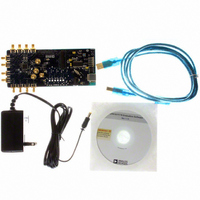
... The AD9516 evaluation board is a compact, easy-to-use platform for evaluating all features of the AD9516. This user guide covers all six versions of the AD9516 family, as well as the AD9517 and AD9518 families (hereafter referred to as AD951x). The AD9516, AD9517, and AD9518 differ only in package size, and the number of outputs ...
Page 2
... Bypassing the Wall Power Supply ............................................... 3 Bypassing the PLL (Clock Distribution Only) ............................. 3 Using an External VCXO ............................................................ 3 Evaluation Board Software .............................................................. 4 Software Installation .................................................................... 4 Running the Software .................................................................. 4 Quick Start Guide to the AD9516 PLL .......................................... 5 Evaluation Software Components .................................................. 7 Main Window ............................................................................... 7 PLL Reference Input Window .................................................... 8 PLL Configuration Window ....................................................... 8 REVISION HISTORY 1/10— ...
Page 3
Evaluation Board User Guide EVALUATION BOARD HARDWARE The following instructions are for setting up the physical connections to the AD951x evaluation board. When connecting the evaluation board for the first time, the user must install the evaluation ...
Page 4
... I/O menu (see Figure 24), and select Ezssp-0, Ezssp-1, or Ezssp-2. Figure 3. Select USB Device Window See the Evaluation Software Components section for a description of the evaluation software features, or the Quick Start Guide to the AD9516 PLL section for details on the individual blocks of the AD951x. Rev Page ...
Page 5
... This quick start guide covers only simple PLL operation to start the PLL. See the AD9516 data sheet and Evaluation Software Components section for a detailed explanation of the various AD9516 features. The following case is an example for the AD9516-3 using the values in Table 1. Table 1. Parameter ...
Page 6
UG-075 6. Program the R (reference) divider by clicking the R DIVIDER box at the top of the main window. Set the desired value and click OK (see Figure 12). 7. Program the N (feedback) divider by clicking the N ...
Page 7
Evaluation Board User Guide EVALUATION SOFTWARE COMPONENTS MAIN WINDOW The AD951x evaluation software is composed of subsections that correspond to the major functional blocks of the AD951x. These subsections are listed in the following sections and each of these has ...
Page 8
... There are many useful diagnostic signals available at these pins. The R divider output is particularly useful. In the example used in the Quick Start Guide to the AD9516 PLL section, the 80 kHz signal is visible on the STATUS pin to ensure that the reference inputs and R divider are working properly. ...
Page 9
Evaluation Board User Guide REGISTER W/R BOX The REGISTER W/R (write/read) box has four buttons and three check boxes. The WRITE button transfers the values stored in the evaluation software to the evaluation board. It blinks red when register values ...
Page 10
UG-075 The evaluation software has internal checking to ensure that invalid settings are not programmed. For example, the B counter must always be larger than the A counter. Another restriction is that 8/9 dual modulus mode cannot be used for ...
Page 11
Evaluation Board User Guide CHANNEL DIVIDER WINDOW The channel divider window shown in Figure 18 is accessed by clicking the appropriate channel divider usually sufficient to change only the divide ratio because the evaluation software and the AD951x ...
Page 12
UG-075 LVDS/CMOS OUTPUT DRIVER WINDOW The LVDS/CMOS Output 6 Settings window shown in Figure 21 is accessed by clicking the OUT6 through OUT9 output driver symbols on the lower right side of the main window. Figure 21. LVDS/CMOS Output 6 ...
Page 13
Evaluation Board User Guide EVALUATION SOFTWARE MENU ITEMS MENU BAR File Menu The File menu has the following options: Load Setup Selecting Load Setup loads a previously saved AD951x setup file (.stp). A setup file is a text file that ...
Page 14
... Figure 27 and those on the evaluation board, as well as the default values for each version of the evaluation board. The Quick Start Guide to the AD9516 PLL section uses these default values. The phase detector frequency is 10 MHz, and the charge pump current for this example is 3 ...
Page 15
... The component values in Table 3 are suitable for applications where the input reference clock is noisy or for cases where the frequency planning requires a phase detector frequency of 1 MHz or lower. Table 3. AD9516 Evaluation Board Low Loop Bandwidth (Clock Cleanup) Filter Component Values ADIsimCLK Component Naming ...
Page 16
UG-075 NOTES ESD CAUTION Evaluation boards are only intended for device evaluation and not for production purposes. Evaluation boards are supplied “as is” and without warranties of any kind, express, implied, or statutory including, but not limited to, any implied ...