IS-DEV KIT-5C NKK Switches, IS-DEV KIT-5C Datasheet - Page 7
IS-DEV KIT-5C
Manufacturer Part Number
IS-DEV KIT-5C
Description
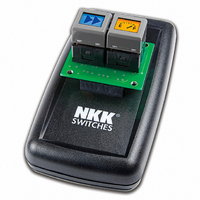
SMARTSWITCH DEVELOPMENT KIT 5C
Manufacturer
NKK Switches
Series
SmartSwitch™r
Datasheet
1.IS-L0251-C.pdf
(24 pages)
Specifications of IS-DEV KIT-5C
Main Purpose
Switches with Programmable Display
Utilized Ic / Part
IS15SBFP4RGB
Primary Attributes
2 LCD Switches, PC Board with Flash Memory
Secondary Attributes
Power and Programming Connections
Description/function
SMARTSWITCH Development Kit
For Use With
360-2431 - SERIAL CBL RJ11-DB9 FOR DEV KIT360-2430 - POWER SUPPLY 240VAC FOR DEV KIT360-2429 - POWER SUPPLY 120VAC FOR DEV KIT
Lead Free Status / RoHS Status
Not applicable / Not applicable
Embedded
-
Lead Free Status / Rohs Status
Lead free / RoHS Compliant
For Use With/related Products
Smart Switch - RGB
Other names
360-2327
IS-DEV KIT-4
IS-DEV KIT-4


7850 East Gelding Drive • Scottsdale, AZ 85260-3420
5. Operational Details
Power-Up Sequence (Steps 1,2,3)
Upon power-up or reset, controller performs the following steps:
Step 1: Check the status of Mode Select Switch for mode of operation. Initialize according to selected mode.
Step 2: Check if the flash RAM has been programmed. Compare the check string to flash RAM string.
Step 3: Write all the default initialize values to the flash memory as follows:
Step 4: LED brightness adjustment as follows:
Main Operational Mode
Step 5:
IS-Dev Kit-5 and IS-Dev Kit-6 Users Manual A.doc
A. If the strings are not the same, the flash RAM is virgin and its data is not acceptable. Step 3 will be
executed. (first time)
B. If the strings are the same, the data from RAM is acceptable. Step 3 is omitted and Step 4 is
executed.
A. Put “BLANK FONT MEMORY” as the picture for location one.
B. Put “BLANK FONT MEMORY” as the picture for location two.
C. Put ONcycle LED’s ON for location #1 and #2.
D. Put OFFcycle LED’s off for location #1 and #2.
E. Put “00H 00H 00H 00H 00H 00H” as attribute for location #1 and #2.
F. Put 00H for software version
G. Write the default setup values such OFFcycle, ON/OFF ratio…
H. Write the virgin check string.
A. Display “DOWN LED” and “UP LED” on the two switches and allow for adjustments of the
B. When the timer expires transmit 83H
C. Initialize and load the data from location 1 and 2 of EEPROM to internal RAM for switch 1 and 2
A. If the switch one is pressed: Transmit 81H to host and execute the attribute.
B. If the switch two is pressed: Transmit 82H to host and execute the attribute.
C. If the timer for switch 1 is expired: Transmit 83H to host and execute the timer attribute.
D. If the timer for switch 2 is expired: Transmit 84H to host and execute the timer attribute.
E. If the switch one is released: Transmit B1H to host.
brightness. There are 8 brightness levels (0 to 7). When the internal timer is expired, the controller
proceeds to Step 5. Every time a switch is pressed, the timer gets reset. If a switch is held
depressed the timer does not run. Switch activity are not reported to host.
respectfully.
(For details see Attribute Execution)
(For details see Attribute Execution)
(For details see Attribute Execution)
(For details see Attribute Execution)
Toll Free 1.877.2BUYNKK (877.228.9655) • Phone 480.991.0942 • Fax 480.998.1435
IS-Dev Kit-5 and IS-Dev Kit-6 Users
www.nkkswitches.com • Email engineering@nkkswitches.com
Manual
Page 7 of 24
1209
Related parts for IS-DEV KIT-5C
Image
Part Number
Description
Manufacturer
Datasheet
Request
R

Part Number:
Description:
KIT DEV FOR LCD 64X32 SWITCH
Manufacturer:
NKK Switches
Datasheet:

Part Number:
Description:
KIT DEV LCD 64X32 COMPACT SWITCH
Manufacturer:
NKK Switches
Datasheet:

Part Number:
Description:
KIT DEV FOR OLED DISPLAY
Manufacturer:
NKK Switches
Datasheet:

Part Number:
Description:
KIT DEV FOR OLED SWITCH
Manufacturer:
NKK Switches
Datasheet:

Part Number:
Description:
BOARD DEV 2RGB SW FLASH & PROGR
Manufacturer:
NKK Switches
Datasheet:

Part Number:
Description:
KIT DEV FOR LCD 64X32 DISPLAY
Manufacturer:
NKK Switches
Datasheet:

Part Number:
Description:
SMARTSWITCH DEVELOPMENT KIT 1
Manufacturer:
NKK Switches
Datasheet:

Part Number:
Description:
SMARTSWITCH DEVELOPMENT KIT 2
Manufacturer:
NKK Switches
Datasheet:

Part Number:
Description:
SMARTSWITCH DEVELOPMENT KIT 5
Manufacturer:
NKK Switches
Datasheet:

Part Number:
Description:
SMARTSWITCH DEVELOPMENT KIT 8
Manufacturer:
NKK Switches
Datasheet:

Part Number:
Description:
LED Displays PROGRAMMABLE SWITCH
Manufacturer:
NKK Switches

Part Number:
Description:
ON-OFF PLATE - SERIES -EMP
Manufacturer:
NKK Switches
Datasheet:

Part Number:
Description:
WRENCH SOCKET FOR KB SERIES PB
Manufacturer:
NKK Switches
Datasheet:

Part Number:
Description:
SWITCH TOGGLE DPST 25A SLDR 5PCS
Manufacturer:
NKK Switches
Datasheet:

Part Number:
Description:
SWITCH TOGGLE DPDT 15A SLDR 5PC
Manufacturer:
NKK Switches
Datasheet: