CPC5621-EVAL-RDL Clare, CPC5621-EVAL-RDL Datasheet - Page 2
CPC5621-EVAL-RDL
Manufacturer Part Number
CPC5621-EVAL-RDL
Description
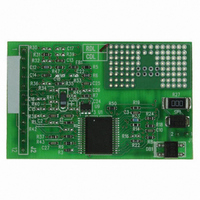
LITELINK III EVALUATION BOARD
Manufacturer
Clare
Series
LITELINK® IIIr
Specifications of CPC5621-EVAL-RDL
Main Purpose
Telecom, Isolation Solution
Embedded
No
Utilized Ic / Part
CPC5621
Primary Attributes
Full-Wave Ringing Detection Phone Line Interface
Secondary Attributes
Resistive AC Termination
Lead Free Status / RoHS Status
Lead free / RoHS Compliant
Other names
CLA164
CPC5621EVAL-RDL
CPC5621EVAL-RDL


LITELINK III Evaluation Board Users Guide
2. Setup
This section describes setting up the LITELINK III
evaluation board prior to use.
2.1 Connection
The LITELINK III evaluation board uses two 0.1 inch
(2.54 mm) pin headers for input and output connec-
tions, J1 and J2. Clare recommends you construct
header jumpers to bring the connections out to your
circuit in development
Table 1: Connector J1 Connections
Table 2: Connector J2 Connections
2
1
2
1
2
3
4
5
6
7
8
9
10
11
12
Pin
Pin
1
2
PWR IN
CODEC CLK
CODEC SIN
CODEC
SOUT
CODEC
SYNC
RESET
OH
CID
RING
911 DET
GND
AUDIO OUT
Silk Screen
Silk Screen
Tip. Connect to telephone network tip
lead.
Ring. Connect to telephone network
ring lead.
Input power for the LITELINK III circuit.
Connect to +5 or +3.3 Vdc
TX+ input to the LITELINK III.
TX- input to the LITELINK III.
RX+ output of the LITELINK III.
RX- output of the LITELINK III.
Not used.
Off hook. Assert low to take the
LITELINK III circuit off hook.
Caller ID. Assert low to engage the
display signal routing features of
LITELINK III.
The output of the LITELINK III ring cir-
cuit. See
for more information.
Loop current detector output.
Host side circuit ground
Not used.
LITELINK datasheets
Use
Use
www.clare.com
3. Using the Evaluation Board
Follow these guidelines for productive use of the
LITELINK evaluation board:
•
•
4. Design Notes
1. The default gain setting at the factory is 0 dB.
2. OH must be de-asserted (set logic high) once at
5. Worldwide Operation
LITELINK III evaluation board AC termination charac-
teristics may be changed by changing stuffing options.
See
CDL Schematic on page
RDL Schematic on page 6
5.1 Stuffing Options
LITELINK III Evaluation Boards can be used to evalu-
ate LITELINK III circuits connected to several types of
host equipment and several types of telephone net-
works. This flexibility will often require changes to the
components in the circuit.
Select and implement a stuffing option as described
below:
Table 3: Stuffing Options
Resistive
Termination
(North
America),
CPC5621-
EVAL-RDL
Make all connections to the board before applying
power.
LITELINK III evaluation board circuit components
are sensitive to electro-static discharge (ESD). Use
normal ESD precautions when working with the
LITELINK III evaluation board.
Option
power-up for 50 ms to transfer internal gain trim
values within LITELINK III. This would be normal
operation in many applications.
Stuffing Options on page
R14 = 499 k
R17 301 ,
R18 = 0 ,
R22 = 8.2 ,
R23 = 150 ,
R24 = 0 ,
Place
5, and
for more information.
2,
CPC5621-EVAL-
CPC5621-EVAL-
C5, C8, C11, R1
Do Not Place
Rev. 2.0
Related parts for CPC5621-EVAL-RDL
Image
Part Number
Description
Manufacturer
Datasheet
Request
R

Part Number:
Description:
LITELINK III EVALUATION BOARD
Manufacturer:
Clare
Datasheet:

Part Number:
Description:
Clare Solar Cells
Manufacturer:
Clare, Inc.
Datasheet:
Part Number:
Description:
Clare Solar Cells
Manufacturer:
Clare, Inc.
Datasheet:
Part Number:
Description:
4 Pin SOP OptoMOS Relay
Manufacturer:
CLARE [Clare, Inc.]
Datasheet:

Part Number:
Description:
MOSFET N-CH 350V 5MA SOT-223
Manufacturer:
Clare
Datasheet:
Part Number:
Description:
MOSFET N-CH 350V 5MA SOT-223
Manufacturer:
Clare
Datasheet:

Part Number:
Description:
IC DRVR PROGRAMMABLE 16-SOIC
Manufacturer:
Clare
Datasheet:

Part Number:
Description:
IC PHONE LINE MONITOR 8-SOIC
Manufacturer:
Clare
Datasheet:

Part Number:
Description:
IC LITELINK III FULL RING 32SOIC
Manufacturer:
Clare
Datasheet:

Part Number:
Description:
LITELINK III PHONE LINE 32SOIC
Manufacturer:
Clare
Datasheet:

Part Number:
Description:
RELAY OPTO TELCOM 12OMA 8-DIP
Manufacturer:
Clare
Datasheet: