SY87739LHI-EVAL Micrel Inc, SY87739LHI-EVAL Datasheet - Page 11
SY87739LHI-EVAL
Manufacturer Part Number
SY87739LHI-EVAL
Description
BOARD EVAL N SY87739 EXPERIMENT
Manufacturer
Micrel Inc
Specifications of SY87739LHI-EVAL
Main Purpose
Timing, Frequency Synthesizer
Embedded
No
Utilized Ic / Part
SY87739
Primary Attributes
Single Integer-N PLL
Secondary Attributes
729MHz, Graphical User Interface, PECL Inputs and Outputs, 3.3V
Lead Free Status / RoHS Status
Lead free / RoHS Compliant
Other names
576-1406
SY87739L-EVAL
SY87739L-EVAL


Micrel, Inc.
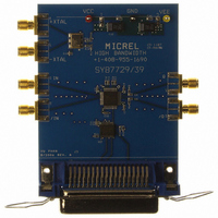
board. U1 is the device being highlighted. The LVPECL
input is DC coupled and terminated via R3, R4, R5 and C6.
This network biases R5 at about 1.3V. Thus, the LVPECL
source driving J3 and J4 sees 50
V
a DC path to ground for the CLKOUT+ and CLKOUT–
LVPELC outputs, while C4 and C5 form the DC block. U3 is
a crystal oscillator that provides differential LVPECL outputs
directly. To use this frequency source, connect J7 to J3 and
J8 to J4.
M9999-071906
hbwhelp@micrel.com or (408) 955-1690
CC
EVALUATION BOARD SCHEMATICS
Figure 19 is the schematic for the SY87729/39L evaluation
–2.0V. The output is AC coupled. R12 and R13 provide
Connector Cent36
19
20
21
22
23
24
25
26
27
28
29
30
31
32
33
34
35
36
REFCLK+
REFCLK—
1
2
3
4
5
6
7
8
9
10
11
12
13
14
15
16
17
18
J9
SMA
SMA
Note:
These four
components
in fly-by
configuration
V
J3
J4
CC
R9
2.21k
C6
0.1 F
R3
51.1
R5
51.1
R4
51.1
Figure 19. SY87729/39L Evaluation Board Schematic
R6
10k
(AC via C6) to about
R7
10k
0.1 F
R8
10k
C13
Note:
Ground relief,
no need for 50 ,
keep near device
0.1 F
C8
0.1 F
V
C9
CC
0.1 F
C14
V
CC
V
CC
1
2
3
4
5
6
7
8
11
VCCA
NC
REFCLK+
REFCLK—
NC
PROGCS
PROGDI
PROGSK
R1
2k
evaluation board to the printer port. When not plugged in,
R9 disables the outputs of U2A, allowing R6, R7, and R8 to
pull down and disable U1’s programming interface. When
J9 pin 4 is low, U2A is enabled, U1 pin 6 is set active high,
and the software on the PC can toggle PROGDI and
PROGSK to effect a configuration download.
pin. Also, one bit from the output, bit 4 (pin 5), is inverted
and sent back to an input on the Centronics interface (pin
11). This is how the applications software determines
whether or not an SY87729/39L evaluation board is attached
to the parallel port.
C2
100nF
32 31 30 29 28 27 26 25
9
7
5
3
2
4
6
8
1
9 10 11 12 13 14 15 16
Y1
Y2
Y3
Y4
U2, a 5V tolerant buffer, interfaces the SY87729/39L
The interface always sees the state of U1’s LOCKED
U2A
74LCX240
A1
A2
A3
A4
G
U2B
74LCX240
U1
SY87729/39L
A1
A2
A3
A4
Y1
Y2
Y3
Y4
G
R2
2k
CLKOUT+
CLKOUT—
11
13
15
17
19
18
16
14
12
VCCA
VCCO
VCC
NC
NC
NC
PROGSK
PROGDI
PROGCS
C3
100nF
24
23
22
21
20
19
18
17
C10
0.1 F
V
CC
Note:
Insert for SY87729L only
Note:
Insert for SY87739L only
C11
0.1 F
V
CC
R10
2.21k
R11
475
V
CC
C7
0.1 F
C12
0.1 F
L1
Ferrite Bead
Note:
R12 and R13 near U1
C1
22 F
R12
121
Note:
In-Line
Note:
R14 and R15 in-line
for back termination
U3
Saronix SEL2431C
1
7
C4
100nF
C5
100nF
/CK
GND
VCC
J1
R13
121
1
Evaluation Board
VCC
CK
R14
DNI
R15
DNI
SY87729/39L
14
8
V
CC
GND
SMA
SMA
SMA
SMA
J2
J5
J6
J7
J8
1
CLKOUT+
CLKOUT—
XTAL—
XTAL+
Related parts for SY87739LHI-EVAL
Image
Part Number
Description
Manufacturer
Datasheet
Request
R

Part Number:
Description:
Manufacturer:
Micrel Inc
Datasheet:
Part Number:
Description:
Manufacturer:
Micrel Inc
Datasheet:
Part Number:
Description:
Manufacturer:
Micrel Inc
Datasheet:
Part Number:
Description:
Manufacturer:
Micrel Inc
Datasheet:
Part Number:
Description:
Manufacturer:
Micrel Inc
Datasheet:
Part Number:
Description:
Manufacturer:
Micrel Inc
Datasheet:
Part Number:
Description:
Manufacturer:
Micrel Inc
Datasheet:
Part Number:
Description:
Manufacturer:
Micrel Inc
Datasheet:
Part Number:
Description:
Manufacturer:
Micrel Inc
Datasheet:
Part Number:
Description:
Manufacturer:
Micrel Inc
Datasheet:
Part Number:
Description:
Manufacturer:
Micrel Inc
Datasheet:
Part Number:
Description:
Manufacturer:
Micrel Inc
Datasheet:
Part Number:
Description:
Manufacturer:
Micrel Inc
Datasheet:
Part Number:
Description:
Manufacturer:
Micrel Inc
Datasheet: