SPUSI2/NOPB National Semiconductor, SPUSI2/NOPB Datasheet - Page 3
SPUSI2/NOPB
Manufacturer Part Number
SPUSI2/NOPB
Description
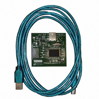
BOARD EVAL DATA CAPTURE BOARD
Manufacturer
National Semiconductor
Specifications of SPUSI2/NOPB
Main Purpose
Interface, Data Capture
Embedded
Yes, MCU, 8-Bit
Utilized Ic / Part
WEBENCH® Sensor Designer Boards
Primary Attributes
USB Interface Dongle II
Secondary Attributes
SPI Interface
Lead Free Status / RoHS Status
Lead free / RoHS Compliant
Other names
SPUSI2
Available stocks
Company
Part Number
Manufacturer
Quantity
Price
Company:

Part Number:
SPUSI2/NOPB
Manufacturer:
National Semiconductor
Quantity:
135


2.0 Power Requirements
The SPUSI2 board requires no external power supply. It is powered by the +5V available
on the USB connector. The +5V is regulated down to +3.3V for the Microcontroller.
The +5V and +3V are available on connector J2 on pins 14 and 13 respectively.
3.0 Setup Procedure
Component Description
Test Points
The following table describes both the on-board connectors and the main
components on the SPUSI2 board.
1. Download Sensor Path Control Panel Software onto your computer prior to
TPG1, TPG2, TPG3, TPG4
connecting board to computer:
http://www.national.com/analog/webench/sensors/spusi2
Component
Test Point
TP10
SW1
TP1
TP2
TP3
TP4
TP5
TP6
TP7
U1
D1
D2
D3
J1
J2
Reset Switch for Microcontroller
USB cable connection
3.3V Power Indicator
USB Microcontroller
Data Flow Indicator
Ready Indicator
3P3V (3.3V)
General -use
Description
Description
Ground
DOUT
SCLK
BKPT
CSB
DIN
PE1
PE0
Related parts for SPUSI2/NOPB
Image
Part Number
Description
Manufacturer
Datasheet
Request
R

Part Number:
Description:
National Semiconductor [8-Bit D/A Converter]
Manufacturer:
National Semiconductor
Datasheet:
Part Number:
Description:
National Semiconductor [Media Coprocessor]
Manufacturer:
National Semiconductor
Datasheet:
Part Number:
Description:
Digitally Controlled Tone and Volume Circuit with Stereo Audio Power Amplifier, Microphone Preamp Stage and National 3D Sound
Manufacturer:
National Semiconductor
Datasheet:
Part Number:
Description:
Digitally Controlled Tone and Volume Circuit with Stereo Audio Power Amplifier, Microphone Preamp Stage and National 3D Sound
Manufacturer:
National Semiconductor
Datasheet:
Part Number:
Description:
AC97 Rev 2 Codec with Sample Rate Conversion and National 3D Sound
Manufacturer:
National Semiconductor
Part Number:
Description:
Manufacturer:
National Semiconductor
Datasheet:
Part Number:
Description:
Manufacturer:
National Semiconductor
Datasheet:
Part Number:
Description:
General Purpose, Low Voltage, Low Power, Rail-to-Rail Output Operational Amplifiers
Manufacturer:
National Semiconductor
Datasheet:
Part Number:
Description:
8-bit 20 MSPS flash A/D converter.
Manufacturer:
National Semiconductor
Datasheet:
Part Number:
Description:
Low Noise Quad Operational Amplifier
Manufacturer:
National Semiconductor
Datasheet:
Part Number:
Description:
Quad Differential Line Receivers
Manufacturer:
National Semiconductor
Datasheet:
Part Number:
Description:
Quad High Speed Trapezoidal? Bus Transceiver
Manufacturer:
National Semiconductor
Datasheet:
Part Number:
Description:
Dual Line Receiver
Manufacturer:
National Semiconductor
Datasheet:
Part Number:
Description:
TTL to 10k ECL Level Translator with Latch
Manufacturer:
National Semiconductor
Datasheet: