USB-MSD-RD Silicon Laboratories Inc, USB-MSD-RD Datasheet
USB-MSD-RD
Specifications of USB-MSD-RD


Related parts for USB-MSD-RD


USB-MSD-RD Summary of contents
Page 1
... USB MSD Reference Design Kit Demonstration”. Detailed descriptions of the components and API functions are included in “AN282: USB Mass Storage Device Reference Design Programmer's Guide". The board hardware is described in sections 6, 7, and 8. Rev. 0.1 5/ Copyright © 2006 by Silicon Laboratories ’ USB-MSD-RD ...
Page 2
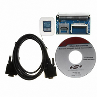
... USB-MSD-RD Figure 1. CF, SD, MMC Memory Expansion Board (AB5) Note: The C8051F340-TB Target Board is not included with the USB-MSD-RD Kit. Figure 2. C8051F340-TB connected to AB5 Expansion Board with SD Card 2 Rev. 0.1 ...
Page 3
... To implement your own application based on this USB MSD Reference Design, you can customize the blocks labeled 'Application', 'Other HW Peripherals', and 'App. Specific Hardware' (all shown in blue in Figure 3). Source code for all the other firmware blocks is also provided, but typically there is no need to customize these blocks. USB-MSD-RD Rev. 0.1 3 ...
Page 4
... USB-MSD-RD Components used only for USB MSD Data Flow USB MSD Data Flow Windows Explorer or Other Application Driver Stack USB Host Controller USB Function Controller USB Mass Storage Device SCSI Media Access C8051F340-TB Target Board Figure 3. USB MSD RD System Architecture 4 File system API serving the Example App ...
Page 5
... Figure 4. USB MSD Firmware Code Space Usage on the C8051F340 File System (5.9 kB) 9% Used (23.9 kB) 38% USB / MSD / SCSI (3.9 kB) 6% Sector Server (1.1 kB) 2% Rev. 0.1 USB-MSD-RD Example Application (5.1 kB) 8% Compiler Libraries / Misc (5.1 kB Media Access (0.7 kB MMC 1% Media Access (2 ...
Page 6
... USB-MSD-RD 5. USB MSD Reference Design Kit Demonstration The following step-by-step demonstration will walk you through the various features and capabilities of this reference design. There are three parts to this demonstration: Firmware Download, Example Application Demonstration, and Mass Storage Device Demonstration. Note: The demonstration instructions assume that a PC running Windows 2000/XP/Server2003 is being used. ...
Page 7
... In the 'Connect using:' drop-down list, Choose 'COM1 you have multiple COM ports, choose the one you want to use. 4. Set up the COM1 Properties dialog as shown in Figure 7, and click OK. Figure 7. Example Application - HyperTerminal Settings USB-MSD-RD → Connect' from the menu to connect to the device. → ...
Page 8
... USB-MSD-RD 5.2.2. Hardware Setup 1. Connect the C8051F340-TB target board connector J13 to the AB5 expansion board connector J1. 2. Insert the SD card provided with the reference design kit into the SD card slot (M2) in the expansion board. 3. Connect a straight DB9 serial cable (RS-232 cable) between the PC's serial port and C8051F340-TB. ...
Page 9
... Figure 9. Example Application - Temperature logging Rev. 0.1 USB-MSD-RD 9 ...
Page 10
... USB-MSD-RD 2. Continue to use the command interpreter shell to log press/release events for the buttons P2.0 and P2.1 on the C8051F340 target board. Follow the steps below and also refer to Figure 10. a. Type "log button.txt" to initiate button press/release logging to a file that is updated every time a button press or release event occurs ...
Page 11
... There should be no need for any user interaction during this phase. At the end of this process, you will see three entries in Device Manager, and you should also see a Removable Disk in Windows Explorer. See Figures 11 and 12. Figure 11. USB Mass Storage Device - Device Manager USB-MSD-RD Rev. 0.1 11 ...
Page 12
... USB-MSD-RD Figure 12. USB Mass Storage Device - Windows Explorer 3. The files created during the previous example application demonstration will be visible. Files can be viewed, added, deleted, copied or moved using Windows Explorer disconnect the device, click on the icon with the green arrow in the system tray and select "Safely Remove USB Mass Storage Device" ...
Page 13
... SD/MMC SPI Master In, Slave Out P0.2 SD/MMC SPI Master Out, Slave In P0.3 SD/MMC SPI Slave Select P1.1 CF Output Enable P1.2 CF Card Enable P1.3 CF Card Detect P1.4 CF Ready Signal P1.0 CF Reset Signal P1.6 CF Write Enable P1.7 Expansion board global power control Rev. 0.1 USB-MSD-RD Description 13 ...
Page 14
... USB-MSD-RD 7. Schematic 14 Rev. 0.1 ...
Page 15
... USB-MSD-RD Rev. 0.1 15 ...
Page 16
... USB-MSD-RD A A—C PPENDIX OMMAND Command Interpreter Shell - Communication Parameters Baud rate: 115200 bps Data format: 8 data bits, 1 stop bit, no parity Flow control: None Command Interpreter Shell - Supported Commands The interactive command interpreter shell presented by the example application via the UART supports a set of MS-DOS-like commands ...
Page 17
... The 'dir' command shows the volume label as a separately entry, with the tag "<LABEL>" shown in the extension column. 5. File creation/modification date and time stamps are not supported when the device is in Embedded System Mode. USB-MSD-RD http://support.microsoft.com/?kbid=142982 Rev. 0.1 17 ...
Page 18
... USB-MSD-RD A B—F PPENDIX ORMATTING A The USB MSD RD firmware supports the FAT16 file system. Memory cards formatted with other file systems cannot be used with this firmware. If the disk is already formatted as FAT16, and you want to reformat the disk, you can do so using the "FORMAT" command available through the Example Application's Command Interpreter Shell. ...
Page 19
... N : OTES USB-MSD-RD Rev. 0.1 19 ...
Page 20
... USB-MSD- ONTACT NFORMATION Silicon Laboratories Inc. 4635 Boston Lane Austin, TX 78735 Tel: 1+(512) 416-8500 Fax: 1+(512) 416-9669 Toll Free: 1+(877) 444-3032 Email: productinfo@silabs.com Internet: www.silabs.com The information in this document is believed to be accurate in all respects at the time of publication but is subject to change without notice. ...