ETHERNETDK Silicon Laboratories Inc, ETHERNETDK Datasheet
ETHERNETDK
Specifications of ETHERNETDK
Available stocks


Related parts for ETHERNETDK

ETHERNETDK Summary of contents
Page 1
E E MBEDDED THERN ET 1. Overview The Embedded Ethernet Development Kit (Ethernet-DK) provides all the hardware and software required to develop real-world embedded Ethernet applications using the industry proven CMX Micronet™ protocol stack and high-performance Silicon Laboratories microcontrollers. The ...
Page 2
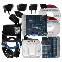
Ethernet-DK 2. Kit Contents The Embedded Ethernet Development Kit contains the following items: C8051F120 Target Board AB4 Ethernet Development Board CAT5e Ethernet Cable Silicon Laboratories Evaluation Kit IDE and Product Information CD-ROM. CD content includes the ...
Page 3
Hardware Setup The following instructions illustrate how to setup the hardware included with the kit. 1. Connect the AB4 Ethernet Development Board to the C8051F120 Target Board at J24 (Figure 2). Apply slight pressure to ensure the mating 96-pin ...
Page 4
Ethernet-DK 4. Network Setup The Embedded Ethernet Development Kit can be connected to an Ethernet network using a standard Ethernet cable (see Figure 4) or directly using a crossover cable (see Figure 5). Table 1 describes the ...
Page 5
Network Setup Procedure If using a standard cable: 1. Connect the AB4 Ethernet Development Board to an Ethernet wall outlet router/switch using a standard Ethernet cable. 2. Connect the same Ethernet network using ...
Page 6
Ethernet-DK 4.2. Selecting an IP Address for the Embedded System For recognize an embedded system on a network, its IP address and subnet mask need to be configured. Below are a few guidelines to follow when choosing ...
Page 7
Software Setup The included CD-ROM contains the Silicon Laboratories IDE, Keil C51 toolset, and documentation including datasheets, application notes, and an electronic version of this user’s guide. The instructions below describe how to install the Embedded Ethernet Development Kit ...
Page 8
Ethernet-DK 4. Unselect the “Install Raisonance Evaluation 8051 Toolset” option and select “Install Keil Evaluation 8051 Toolset”. Then press the Install button. 5. Follow the installation prompts to install the development tools. The following applications will be installed: The Silicon ...
Page 9
Embedded Ethernet Tutorial Now that the Embedded Ethernet Development Kit hardware has been set up, the software installed, and the embedded system connected to a network time to download firmware into the MCU and test its network ...
Page 10
Ethernet- the System Settings section of the left window, select IP Addresses the right window, set the Source IP Address to the IP address of the embedded system the Gateway IP Address and Subnet ...
Page 11
Save the selected configuration using the FileSave As menu. 10. Generate a new project with supporting firmware by selecting Generate Project from the File menu (see Figure 9). 11. When prompted for a folder to save the project, browse ...
Page 12
Ethernet-DK 6.1.2. Programming the MCU We will now build the project created by the TCP/IP Configuration Wizard and download the firmware to the MCU using the Silicon Laboratories IDE. 1. From the Windows Start menu, start the Silicon Laboratories IDE. ...
Page 13
Verify the Compiler and Linker tabs are pointing to the C51.exe (compiler) and BL51.exe (linker) files in C:\Keil\C51\BIN in the Executable field. 6. Press the Compiler tab's Customize button. Under the Variable Location drop down box, select Large: XDATA ...
Page 14
Ethernet-DK 8. Click the Connect button in the toolbar or select DebugConnect from the menu. Note: If you receive the error message “Communication could not be established with the specified serial adapter”, open the Connection Options Dialog by selecting OptionsConnection ...
Page 15
Testing Connectivity Using PING After pressing GO, the MCU will be executing the TCP/IP stack firmware. The LEDs on the RJ-45 Ethernet connector should light up if the MCU is connected to a network. Once the network router detects ...
Page 16
Ethernet-DK 6.2. Stage 2—Basic Web Server with DHCP and Netfinder Capability In the first stage of the demo, we learned how to generate firmware for an embedded web server using the TCP/IP Configuration Wizard and access the embedded server from ...
Page 17
Save the selected configuration using the FileSave As menu. 6. Generate a new project with supporting firmware by selecting Generate Project from the File menu (see Figure 13). 7. When prompted for a folder to save the project, browse ...
Page 18
Ethernet-DK 6.2.2. Programming the MCU We will now build the project created by the TCP/IP Configuration Wizard and download the firmware to the MCU using the Silicon Laboratories IDE. 1. From the Windows Start menu, start the Silicon Laboratories IDE. ...
Page 19
Verify the Compiler and Linker tabs are pointing to the C51.exe (compiler) and BL51.exe (linker) files in C:\Keil\C51\BIN in the Executable field. 6. Press the Compiler tab's Customize button. Under the Variable Location drop down box, select Large: XDATA ...
Page 20
Ethernet-DK 8. Click the Connect button in the toolbar or select DebugConnect from the menu. Note: If you receive the error message “Communication could not be established with the specified serial adapter”, open the Connection Options Dialog by selecting OptionsConnection ...
Page 21
Finding the Embedded System We will now search for embedded systems on the network. Note: The Netfinder utility v1.0 is not compatible with Windows Vista or Windows 7. 1. Open the Netfinder utility found in C:\SiLabs\MCU\Utilities\Netfinder. 2. Press the ...
Page 22
Ethernet-DK 5. The default web browser should launch and display the home page served by the embedded web server. The same result can be achieved by typing the IP address of the embedded web server into the address bar of ...
Page 23
Enter the IP address, subnet mask, and default gateway (if known) into the ‘Assign IP Address’ dialog and press OK. See Appendix A for information on how to configure the PC with a static IP address and how to ...
Page 24
Ethernet-DK 10. The default web browser should launch and display the home page served by the embedded web server. The same result can be achieved by typing the IP address of the embedded web server into the address bar of ...
Page 25
Stage 3—Configuring MAC and IP Addresses over the Serial Port In the first two stages of the demo, we learned how to generate firmware for an embedded web server using the TCP/IP Configuration Wizard and access the embedded server ...
Page 26
Ethernet-DK 6.3.3. Programming the IP Address Now the MCU will be running the new firmware and blinking the green LED (P1.6) to indicate that the IP address has not been programmed. In this mode, the MCU is waiting for the ...
Page 27
Stage 4—Adding Web Server Content In the first three stages of the demo, we learned how to make an embedded web server, find it on the network using Netfinder, and program its IP over the serial port. In this ...
Page 28
Ethernet-DK 6.4.3. Re-Building the Project and Viewing Results Once the file arrays are updated time to re-build the project and view the results. 1. Open and re-build the project. This can be done by selecting ProjectOpen Project and ...
Page 29
Figure 26. µWeb Embedded Web Server Rev. 0.6 Ethernet-DK 29 ...
Page 30
Ethernet-DK 7. Example Source Code The Embedded Ethernet Development Kit includes example source code, libraries, and register definition files for all MCU devices. These examples are installed by default in the “C:\SiLabs\MCU\Examples” directory during IDE installation. Inside this directory, an ...
Page 31
C8051F120 Target Board The Embedded Ethernet Development Kit includes a target board with a C8051F120 device pre-installed for evaluation and software development. Numerous input/output (I/O) connections are provided to facilitate prototyping using the target board. Refer to Figure 27 ...
Page 32
Ethernet-DK 8.1. C8051F120 Target Board Schematic 32 Rev. 0.6 ...
Page 33
AB4 Ethernet Development Board The Embedded Ethernet Development Kit includes the AB4 Ethernet Development Board designed to connect the C8051F120 (or C8051F340, C8051F020, C8051F040, or C8051F060) target board to an ethernet network. The ethernet controller used is the CP2200. ...
Page 34
Ethernet-DK 9.1. Expansion I/O Connector (J1) The 96-pin expansion I/O connector J1 is used to connect the AB4 Ethernet Development Board to the C8051F120 Target Board. J1 provides access to many C8051F120 signal pins. Pins for +3 V, digital ground, ...
Page 35
AB4 Board Schematic Ethernet-DK Rev. 0.6 35 ...
Page 36
Ethernet-DK 10. Silicon Laboratories IDE (Integrated Development Environment) The Silicon Laboratories IDE integrates a source-code editor, source-level debugger and in-system Flash programmer. The use of third-party compilers and assemblers is also supported. This development kit includes the Keil Software A51 ...
Page 37
A —S PPENDIX UPPORTED Link/Physical Layer: Ethernet (IEEE802.3)—Widely installed local area network link/physical layer. Internet Layer: IP (Internet Protocol)—IP specifies the format of packets and manages the addressing of all devices on the network included in all builds ...
Page 38
Ethernet- OCUMENT HANGE IST Revision 0.3 to Revision 0.4 Added Netfinder Example. Added note that R1 should be shorted with a zero ohm resistor on the 'F12x Target Board. Updated the supported protocols in ...
Page 39
N : OTES Ethernet-DK Rev. 0.6 39 ...
Page 40
... Should Buyer purchase or use Silicon Laboratories products for any such unintended or unauthorized ap- plication, Buyer shall indemnify and hold Silicon Laboratories harmless against all claims and damages. Silicon Laboratories and Silicon Labs are trademarks of Silicon Laboratories Inc. Other products or brandnames mentioned herein are trademarks or registered trademarks of their respective holders. ...