MAX3420EEVKIT-2+ Maxim Integrated Products, MAX3420EEVKIT-2+ Datasheet - Page 4
MAX3420EEVKIT-2+
Manufacturer Part Number
MAX3420EEVKIT-2+
Description
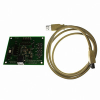
EVAL KIT FOR MAX3420E
Manufacturer
Maxim Integrated Products
Specifications of MAX3420EEVKIT-2+
Main Purpose
Interface, USB 2.0 Slave
Embedded
No
Utilized Ic / Part
MAX3420E
Primary Attributes
Full Speed (12Mbps), SPI Interface, No Custom USB Drivers
Secondary Attributes
4 GPI Pushbuttons, 4 GPO LEDs
Lead Free Status / RoHS Status
Lead free / RoHS Compliant


MAX3420E Evaluation Kit-2
Table 3. SPI Bus Selection (JU1–JU5)
*Default position.
Table 4. GPO 0–3 LED Connection (JU6–JU9)
*Default position.
Table 5. V
*Default position.
Table 6. Power-Supply Source Selection
*Default position.
4
_______________________________________________________________________________________
JUMPER
JUMPER
JUMPER
JUMPER
JU10
JU1
JU2
JU3
JU4
JU5
JU11
JU6
JU7
JU8
JU9
L
Logic-Supply Selection (V
SHUNT POSITION
SHUNT POSITION
SHUNT POSITION
SHUNT POSITION
Open
Open
Open
Open
Open
1-2*
1-2*
1-2*
1-2*
1-2*
Open
1-2*
1-2*
1-2*
1-2*
2-3
2-3
2-3
2-3
2-3
1-2*
2-3
1-2*
2-3
INT line connected to the ATtiny2313 INT line
INT line connected to H1-2
SS line connected to the ATtiny2313 SS line
SS line connected to H1-6
MOSI line connected to the ATtiny2313 MOSI line
MOSI line connected to H1-4
MISO line connected to the ATtiny2313 MISO line
MISO line connected to H1-3
SCLK line connected to the ATtiny2313 SCLK line
SCLK line connected to H1-5
EV kit-2 board powered by USB
Do not use
Apply 5V supply on JU11-2 and GND on JU11-3
GPO port 3 LED (D4) connected
GPO port 3 LED (D4) disconnected
GPO port 2 LED (D3) connected
GPO port 2 LED (D3) disconnected
GPO port 1 LED (D2) connected
GPO port 1 LED (D2) disconnected
GPO port 0 LED (D1) connected
GPO port 0 LED (D1) disconnected
Logic-supply voltage (V
Do not use
Apply V
L
L
)
supply on H1-9
L
= 3.3V)
DESCRIPTION
DESCRIPTION
DESCRIPTION
DESCRIPTION
Related parts for MAX3420EEVKIT-2+
Image
Part Number
Description
Manufacturer
Datasheet
Request
R

Part Number:
Description:
MAX7528KCWPMaxim Integrated Products [CMOS Dual 8-Bit Buffered Multiplying DACs]
Manufacturer:
Maxim Integrated Products
Datasheet:
Part Number:
Description:
Single +5V, fully integrated, 1.25Gbps laser diode driver.
Manufacturer:
Maxim Integrated Products
Datasheet:
Part Number:
Description:
Single +5V, fully integrated, 155Mbps laser diode driver.
Manufacturer:
Maxim Integrated Products
Datasheet:
Part Number:
Description:
VRD11/VRD10, K8 Rev F 2/3/4-Phase PWM Controllers with Integrated Dual MOSFET Drivers
Manufacturer:
Maxim Integrated Products
Datasheet:
Part Number:
Description:
Highly Integrated Level 2 SMBus Battery Chargers
Manufacturer:
Maxim Integrated Products
Datasheet:
Part Number:
Description:
Current Monitor and Accumulator with Integrated Sense Resistor; ; Temperature Range: -40°C to +85°C
Manufacturer:
Maxim Integrated Products
Part Number:
Description:
TSSOP 14/A�/RS-485 Transceivers with Integrated 100O/120O Termination Resis
Manufacturer:
Maxim Integrated Products
Part Number:
Description:
TSSOP 14/A�/RS-485 Transceivers with Integrated 100O/120O Termination Resis
Manufacturer:
Maxim Integrated Products
Part Number:
Description:
QFN 16/A�/AC-DC and DC-DC Peak-Current-Mode Converters with Integrated Step
Manufacturer:
Maxim Integrated Products
Part Number:
Description:
TDFN/A/65V, 1A, 600KHZ, SYNCHRONOUS STEP-DOWN REGULATOR WITH INTEGRATED SWI
Manufacturer:
Maxim Integrated Products
Part Number:
Description:
Integrated Temperature Controller f
Manufacturer:
Maxim Integrated Products
Part Number:
Description:
SOT23-6/I�/45MHz to 650MHz, Integrated IF VCOs with Differential Output
Manufacturer:
Maxim Integrated Products
Part Number:
Description:
SOT23-6/I�/45MHz to 650MHz, Integrated IF VCOs with Differential Output
Manufacturer:
Maxim Integrated Products
Part Number:
Description:
EVALUATION KIT/2.4GHZ TO 2.5GHZ 802.11G/B RF TRANSCEIVER WITH INTEGRATED PA
Manufacturer:
Maxim Integrated Products
Part Number:
Description:
QFN/E/DUAL PCIE/SATA HIGH SPEED SWITCH WITH INTEGRATED BIAS RESISTOR
Manufacturer:
Maxim Integrated Products
Datasheet: