NCV7708AGEVB ON Semiconductor, NCV7708AGEVB Datasheet
NCV7708AGEVB
Manufacturer Part Number
NCV7708AGEVB
Description
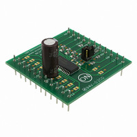
EVAL BOARD FOR NCV7708AG
Manufacturer
ON Semiconductor
Specifications of NCV7708AGEVB
Design Resources
NCV7708 EVB BOM NCV7708GEVB Gerber Files NCV7708 EVB Schematic
Main Purpose
Power Management, Half H-Bridge Driver (Internal FET)
Embedded
No
Utilized Ic / Part
NCV7708
Primary Attributes
6 Channel High & Low Side Internal Switch
Secondary Attributes
SPI Interface
Silicon Manufacturer
On Semiconductor
Silicon Core Number
NCV7708A
Kit Application Type
Driver - Bridge
Application Sub Type
Half Bridge Driver
Development Tool Type
Hardware - Eval/Demo Board
Rohs Compliant
No
Lead Free Status / RoHS Status
Lead free / RoHS Compliant
For Use With/related Products
NCV7708AG
Other names
NCV7708AGEVBOS


Test Procedure
7/24/2008
Terminology
1. Assemble target PCB with test pins on the bottom to mate with test fixture – don’t trim
2. Remove the “EN” jumper block from the target.
3. Mate the target with the test fixture.
4. Connect the fixture to a computer’ parallel port – desktop PC is preferred over laptop PC.
5. Connect a 14 V power supply to the test fixture and turn it on.
6. Check that both the 14V and 5V power LEDs on the fixture are illuminated.
7. Launch the NCV7708 GUI on the computer.
8. Connect a scope or DVM to the “EN” test pin and GND on the target – set the scope for 5
9. Check that the “EN” signal level is ~ 0 V – logic low.
10. Left-click the “Enable/Disable” button in the GUI.
11. Check that the “EN” signal level is ~ 5 V – logic high – proceed to step 14 if OK.
Target PCB – PCB with NCV7708A to be tested
Test Fixture – mates with target and computer
GUI – Graphical User Interface software for the NCV7708A
the pins at the top, you’ll need to connect your instruments to them.
V/div vertical, 50 us/div horizontal, auto trigger.
Test Procedure for the NCC7708 Evaluation Board
Figure 1: Test Setup
- 1 -
www.onsemi.com
Related parts for NCV7708AGEVB
Image
Part Number
Description
Manufacturer
Datasheet
Request
R

Part Number:
Description:
The NCV7708A is a fully protected Hex Half Bridge Driver designed specifically for automotive and industrial motion control applications. The six low and high side drivers are freely configurable and can be controlled separately. This allows for high
Manufacturer:
ON Semiconductor
Datasheet:
Part Number:
Description:
The NCV7708 is a fully protected Hex Half Bridge Driver designed specifically for automotive and industrial motion control applications. The six low and high side drivers are freely configurable and can be controlled separately. This allows for high
Manufacturer:
ON Semiconductor
Datasheet:
Part Number:
Description:
ON Semiconductor [VOLTAGE REGULATOR]
Manufacturer:
ON Semiconductor
Datasheet:
Part Number:
Description:
357-036-542-201 CARDEDGE 36POS DL .156 BLK LOPRO
Manufacturer:
ON Semiconductor
Datasheet:
Part Number:
Description:
357-036-542-201 CARDEDGE 36POS DL .156 BLK LOPRO
Manufacturer:
ON Semiconductor
Datasheet:
Part Number:
Description:
357-036-542-201 CARDEDGE 36POS DL .156 BLK LOPRO
Manufacturer:
ON Semiconductor
Datasheet:
Part Number:
Description:
357-036-542-201 CARDEDGE 36POS DL .156 BLK LOPRO
Manufacturer:
ON Semiconductor
Datasheet:
Part Number:
Description:
357-036-542-201 CARDEDGE 36POS DL .156 BLK LOPRO
Manufacturer:
ON Semiconductor
Datasheet:
Part Number:
Description:
357-036-542-201 CARDEDGE 36POS DL .156 BLK LOPRO
Manufacturer:
ON Semiconductor
Datasheet:
Part Number:
Description:
357-036-542-201 CARDEDGE 36POS DL .156 BLK LOPRO
Manufacturer:
ON Semiconductor
Datasheet:
Part Number:
Description:
357-036-542-201 CARDEDGE 36POS DL .156 BLK LOPRO
Manufacturer:
ON Semiconductor
Datasheet:
Part Number:
Description:
357-036-542-201 CARDEDGE 36POS DL .156 BLK LOPRO
Manufacturer:
ON Semiconductor
Datasheet:
Part Number:
Description:
357-036-542-201 CARDEDGE 36POS DL .156 BLK LOPRO
Manufacturer:
ON Semiconductor
Datasheet:
Part Number:
Description:
Manufacturer:
ON Semiconductor
Datasheet:
NCV7708AGEVB Summary of contents
Page 1
Test Procedure for the NCC7708 Evaluation Board Terminology Target PCB – PCB with NCV7708A to be tested Test Fixture – mates with target and computer GUI – Graphical User Interface software for the NCV7708A Test Procedure 1. Assemble target PCB ...
Page 2
If the “EN” signal did not change states in step 11, trace the signal path as shown in the interface schematic (last page) back to U2 pin 11 and to the connector on the test fixture. 13. If the ...
Page 3
Figure 3: Test Fixture Schematic - 3 - www.onsemi.com ...