EVB-USB2524 SMSC, EVB-USB2524 Datasheet
EVB-USB2524
Specifications of EVB-USB2524
Available stocks


Related parts for EVB-USB2524


EVB-USB2524 Summary of contents
Page 1
... PROFITS, SAVINGS OR REVENUES OF ANY KIND; REGARDLESS OF THE FORM OF ACTION, WHETHER BASED ON CONTRACT; TORT; NEGLIGENCE OF SMSC OR OTHERS; STRICT LIABILITY; BREACH OF WARRANTY; OR OTHERWISE; WHETHER OR NOT ANY REMEDY OF BUYER IS HELD TO HAVE FAILED OF ITS ESSENTIAL PURPOSE, AND WHETHER OR NOT SMSC HAS BEEN ADVISED OF THE POSSIBILITY OF SUCH DAMAGES. SMSC EVB-USB2524 Revision 0.9 (09-28-06) ...
Page 2
... LED status options, and non-removable or disabled configuration for each port. The manufacturer, product and serial strings for the hub can be changed in the EEPROM as well. The EVB-USB2524 can also be configured through changing population of resistors to access internal “strapping options”, without using the EEPROM. ...
Page 3
... Port Assignment The EVB-USB2524 port assignments are selected by four level switches SW1 to SW4 located in the upper right-hand corner. When only one up-stream port, “US 1” or “US 2” is connected to an operational host, all down-stream ports will be assigned to that host. In this case the switches do not have any effect. When both up-stream ports are connected to operational hosts “ ...
Page 4
... Hardware Configuration The EVB-USB2524 has two sets of resistor jumpers. The first set selects the USB2524 configuration; internal defaults, SMBus slave or EEPROM configuration. The second set enables dual LED mode. 3.1 USB2524 Configuration Selection The USB2524 has three configuration pins CFG_SEL[2:0], that determines the operating mode of the USB2524. The selection of a configuration is done with six resistor combinations shown in Table 3 ...
Page 5
... LED Configuration The USB2524 supports three different modes for LED indicators: USB, Basic and DUAL LED. The EVB-USB2524 is configured for Basic LED operation, which means that eight LEDs are used to signal port assignment. Each down- stream port has one green and one red LED. When the port is assigned to up-stream port 1 the green LED is lit. ...
Page 6
... Port is assigned and operating at LS/FS speed ON OFF Port is assigned and operating at High speed ON ON Port is assigned to unattached upstream port Note: Revision 0.9 (09-28-06) EVB-USB2524 Evaluation Board Revision B1 Port Status The USB2524 sends a continuos 1kHz pulse train in this state. SECURITY LEVEL 6 SMSC EVB-USB2524 ...
Page 7
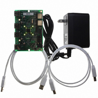
... EVB-USB2524 Evaluation Board Revision B1 4 Connector Description The EVB-USB2524 has a standard set of USB style connectors, two of type B for upstream ports and four of type A for downstream ports. Power is supplied via a 2.0 mm power jack. There are three pin strip header blocks for external hardware to access the USB2524. Table 4.1 lists all the connectors. ...
Page 8
... Revision 0.9 (09-28-06) Figure 4.1 EVB-USB2524 PCB layout SECURITY LEVEL 8 EVB-USB2524 Evaluation Board Revision B1 SMSC EVB-USB2524 ...