MCP73871EV Microchip Technology, MCP73871EV Datasheet - Page 22
MCP73871EV
Manufacturer Part Number
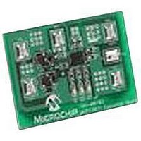
MCP73871EV
Description
EVALUATION BOARD FOR MCP73871
Manufacturer
Microchip Technology
Type
Battery Managementr
Specifications of MCP73871EV
Main Purpose
Power Management, Battery Charger
Embedded
No
Utilized Ic / Part
MCP73871
Primary Attributes
1 Cell- Li-Ion / Li-Pol, 4.2V @ 100 or 500mA: USB, 1.65A: AC Adaptor
Secondary Attributes
LED Status Indicators
Silicon Manufacturer
Microchip
Application Sub Type
Battery Charger
Kit Application Type
Power Management - Battery
Silicon Core Number
MCP73871
Product
Power Management Modules
Kit Contents
Board
Lead Free Status / RoHS Status
Lead free / RoHS Compliant
For Use With/related Products
MCP73871
Lead Free Status / RoHS Status
Lead free / RoHS Compliant


MCP73871
4.12
If the voltage on the IN pin drops to a preset value,
determined by the threshold established at the VPCC
input, due to a limited amount of input current or input
source impedance, then the battery charging current is
reduced. The VPCC control tries to reach a
steady-state condition where the system load has
priority and the battery is charged with the remaining
current. Therefore, if the system demands more
current than the input can provide, the ideal diode will
become forward biased and the battery is able to
supplement the input current to the system load.
The VPCC sustains the system load as its highest
priority. It does this by reducing the noncritical charge
current while maintaining the maximum power output of
the adapter. Further demand from the system is
supported by the battery, if possible.
The VPCC feature functions identically for USB port or
ac-dc adapter inputs. This feature can be disabled by
connecting the VPCC to IN pin.
DS22090B-page 22
Voltage Proportional Charge
Control (VPCC)
4.13
If the input current threshold is reached, then the
battery charging current is reduced. The ICLC tries to
reach a steady-state condition where the system load
has priority and the battery is charged with the
remaining current. No active control limits the current
to the system. Therefore, if the system demands more
current than the input can provide or the input ICLC is
reached, the ideal diode will become forward biased
and the battery is able to supplement the input current
to the system load.
The ICLC sustains the system load as its highest
priority. This is done by reducing the non-critical charge
current while adhering to the current limits governed by
the USB specification or the maximum ac-dc adapter
current supported. Further demand from the system is
supported by the battery, if possible.
FIGURE 4-4:
USB Port.
-100
-200
700
600
500
400
300
200
100
0
Input Current Limit Control (ICLC)
0
100 200 300 400 500 600 700
Load Current (mA)
Input Current Limit Control -
© 2009 Microchip Technology Inc.
Ideal
Diode
Input Current
Battery Current
Load Current
Related parts for MCP73871EV
Image
Part Number
Description
Manufacturer
Datasheet
Request
R

Part Number:
Description:
Manufacturer:
Microchip Technology Inc.
Datasheet:
Part Number:
Description:
Manufacturer:
Microchip Technology Inc.
Datasheet:
Part Number:
Description:
Manufacturer:
Microchip Technology Inc.
Datasheet:
Part Number:
Description:
Manufacturer:
Microchip Technology Inc.
Datasheet:
Part Number:
Description:
Manufacturer:
Microchip Technology Inc.
Datasheet:
Part Number:
Description:
Manufacturer:
Microchip Technology Inc.
Datasheet:
Part Number:
Description:
Manufacturer:
Microchip Technology Inc.
Datasheet:
Part Number:
Description:
Manufacturer:
Microchip Technology Inc.
Datasheet: