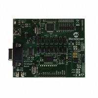
MCP2150DM Microchip Technology, MCP2150DM Datasheet - Page 18

MCP2150DM
Manufacturer Part Number
MCP2150DM
Description
BOARD DEMO FOR MCP2150
Manufacturer
Microchip Technology
Specifications of MCP2150DM
Main Purpose
Interface, IrDA
Embedded
Yes, MCU, 8-Bit
Utilized Ic / Part
MCP2150
Primary Attributes
IrDA Controller with PIC18F MCU
Secondary Attributes
USB Interface
Processor To Be Evaluated
MCP2150, MCP2155
Processor Series
MCP215x
Interface Type
USB
Lead Free Status / RoHS Status
Lead free / RoHS Compliant
Lead Free Status / RoHS Status
Lead free / RoHS Compliant, Lead free / RoHS Compliant
MCP2150
2.10
The MCP2150 emulates a null modem connection. The
application on the DTE device sees a virtual serial port.
This serial port emulation is provided by the IrDA stan-
dard protocols. The link between the DTE device and
the
MCP2150. The connection between the MCP2150 and
the embedded application is wired as if there were a
null modem connection.
The Carrier Detect (CD) signal of the MCP2150 is used
to indicate that a valid IrDA standard infrared link has
been established between the MCP2150 and the Pri-
mary device. The CD signal should be monitored
closely to make sure that any communication tasks can
be completed. The MCP2150 DSR signal indicates that
the device has powered-up, successfully initialized and
is ready for service. This signal is intended to be con-
nected to the DSR input of the Host Controller. If the
Host Controller was directly connected to an IrDA stan-
dard Primary device using a serial cable (the MCP2150
is not present), the Host Controller would be connected
to the Primary device’s DTR output signal.
The MCP2150 generates the CTS signal locally
because of buffer limitations.
2.10.1
The MCP2150 uses a 64-byte buffer for incoming data
from the IR Host. Another 64-byte buffer is provided to
buffer data from the UART serial port. When an IR
packet begins the IrComm, the MCP2150 handles IR
data exclusively (the UART serial port buffer is not
available). A hardware handshaking pin (CTS) is pro-
vided to inhibit the Host Controller from sending serial
data while IR Data is being sent or received.
TABLE 2-4:
DS21655B-page 18
Note 1: Number of bytes calculated based on a common turnaround time of 1 ms.
Data Packet
Size (Bytes)
Note:
MCP2150
Note 1: The
embedded application is made using the
64
1
Operation
2: Only transceiver’s TXD and RXD signals
When the CTS output from the IrComm is
high, no data should be sent from the Host
Controller. The UART FIFO will store up to
2 bytes. Any additional data bytes will be
lost.
HARDWARE HANDSHAKING
signals locally.
are carried back and forth to the Primary
device. The MCP2150 emulates a 3-wire
serial connection (TXD, RXD and GND).
Overhead
(Bytes)
THEORETICAL IrDA STANDARD THROUGHPUT EXAMPLES @ 115.2 KBAUD
MCP2150
8
8
Response (Bytes)
Primary Device
generates
Minimum
6
6
non-data
Turn-around Time
Preliminary
Primary Device
(Bytes)
12
12
2.10.2
The maximum IR data rate of the MCP2150 is
115.2 kbaud. The actual throughput will be less, due to
several factors. The most significant factors are under
the control of the developer. One factor beyond the
control of the designer is the overhead associated with
the IrDA standard. The MCP2150 uses a fixed data
block size of 64 bytes. To carry 64 bytes of data, the
MCP2150 must send 72 bytes (64+8). The additional 8
bytes are used by the protocol. When the Primary
device receives the frame, it must wait for a minimum
latency period before sending a packet of its own. This
turnaround time is set by IrLAP when the parameters of
the link are negotiated. A common turnaround time is
1 ms, although longer and shorter times may be
encountered. 1 ms represents approximately 12 byte
times at a data rate of 115.2 kbaud. The minimum size
frame the Primary device can respond with is 6 bytes.
The MCP2150 will add the 12 byte-time latency on its
own, again assuming a 1 ms latency. This means that
the maximum throughput will be 64 data bytes out of a
total of 64 + 38 byte times. Thus, the maximum theoret-
ical throughput will be limited to about 64/(64+38)=63%
of the IR data rate. Actual maximum throughput will be
dependent
characteristics of the Primary device.
The most significant factor in data throughput is how
well the data frames are filled. If only 1 byte is sent at a
time, then the maximum throughput is 1/(1+38)=2.5%
of the IR data rate. The best way to maximize through-
put is to align the amounts of data with the packet size
of the MCP2150. Throughput examples are shown in
Table
Note:
(1)
2-4.
Time
Turn-around
MCP2150
IrDA throughput is based on many factors
associated with characteristics of the Pri-
mary and Secondary devices. These char-
acteristics may cause your application
throughput to be less than the theoretical
example shown in
BUFFERS AND THROUGHPUT
on
(1)
12
12
(Bytes)
both
Transmitted
Total Bytes
the
2002 Microchip Technology Inc.
102
Table
39
MCP2150
2-4.
% (Data/Total)
Throughput
62.7%
2.6%
and
the


