MCP3905RD-PM1 Microchip Technology, MCP3905RD-PM1 Datasheet - Page 5
MCP3905RD-PM1
Manufacturer Part Number
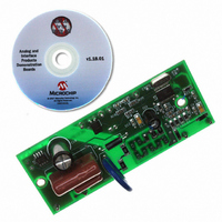
MCP3905RD-PM1
Description
REFERENCE DESIGN FOR MCP3905
Manufacturer
Microchip Technology
Specifications of MCP3905RD-PM1
Main Purpose
Power Management, Energy/Power Meter
Embedded
No
Utilized Ic / Part
MCP3905/6
Primary Attributes
1-Phase, 220 VAC, In Case, With Mechanical Counter
Secondary Attributes
On Board Transformerless AC/DC 5V Supply
Silicon Manufacturer
Microchip
Silicon Core Number
MCP3905A,MCP3906A
Kit Application Type
Power Management
Application Sub Type
Energy Meter
Kit Contents
Design Guides
Lead Free Status / RoHS Status
Lead free / RoHS Compliant
Available stocks
Company
Part Number
Manufacturer
Quantity
Price
Company:

Part Number:
MCP3905RD-PM1
Manufacturer:
MICROCHIP
Quantity:
12 000


INTRODUCTION
DOCUMENT LAYOUT
© 2009 Microchip Technology Inc.
All documentation becomes dated, and this manual is no exception. Microchip tools and
documentation are constantly evolving to meet customer needs, so some actual dialogs
and/or tool descriptions may differ from those in this document. Please refer to our web site
(www.microchip.com) to obtain the latest documentation available.
Documents are identified with a “DS” number. This number is located on the bottom of each
page, in front of the page number. The numbering convention for the DS number is
“DSXXXXXA”, where “XXXXX” is the document number and “A” is the revision level of the
document.
For the most up-to-date information on development tools, see the MPLAB
Select the Help menu, and then Topics to open a list of available on-line help files.
This chapter contains general information that will be useful to know before using the
MCP3905A/06A Energy Meter Reference Design. Items discussed in this chapter
include:
• Document Layout
• Conventions Used in this Guide
• Recommended Reading
• The Microchip Web Site
• Customer Support
• Document Revision History
This document describes how to use the MCP3905A/06A Energy Meter Reference
Design as a development tool to emulate and debug firmware on a target board. The
manual layout is as follows:
• Chapter 1. “Product Overview” – Important information about the
• Chapter 2. “Installation and Operation” – Provides a detailed description of
• Appendix A. “Schematics and Layouts” – Shows the schematic and board
• Appendix B. “Bill Of Materials (BOM)” – Lists the parts used to build the
MCP3905A/06A Energy Meter Reference Design.
each block, as well as instructions on how to get started with this board.
layout diagrams for the MCP3905A/06A Energy Meter Reference Design.
MCP3905A/06A Energy Meter Reference Design.
NOTICE TO CUSTOMERS
MCP3905A/06A ENERGY METER
Preface
REFERENCE DESIGN
®
IDE on-line help.
DS51565B-page 1
Related parts for MCP3905RD-PM1
Image
Part Number
Description
Manufacturer
Datasheet
Request
R

Part Number:
Description:
IC ENERGY METER 24-SSOP
Manufacturer:
Microchip Technology
Datasheet:

Part Number:
Description:
Energy-Metering ICs with Active (Real) Power Pulse Output
Manufacturer:
Microchip Technology
Part Number:
Description:
(MCP3905 / MCP3906) Energy-Metering ICs
Manufacturer:
Microchip Technology
Datasheet:

Part Number:
Description:
Manufacturer:
Microchip Technology Inc.
Datasheet:
Part Number:
Description:
Manufacturer:
Microchip Technology Inc.
Datasheet:
Part Number:
Description:
Manufacturer:
Microchip Technology Inc.
Datasheet:
Part Number:
Description:
Manufacturer:
Microchip Technology Inc.
Datasheet:
Part Number:
Description:
Manufacturer:
Microchip Technology Inc.
Datasheet:
Part Number:
Description:
Manufacturer:
Microchip Technology Inc.
Datasheet:
Part Number:
Description:
Manufacturer:
Microchip Technology Inc.
Datasheet: