MCP215XDM Microchip Technology, MCP215XDM Datasheet - Page 48
MCP215XDM
Manufacturer Part Number
MCP215XDM
Description
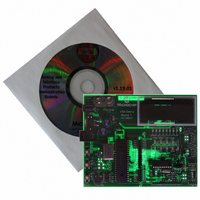
BOARD DEMO FOR MCP215X
Manufacturer
Microchip Technology
Specifications of MCP215XDM
Main Purpose
Interface, IrDA
Embedded
Yes, MCU, 8-Bit
Utilized Ic / Part
MCP2150, MCP2155
Primary Attributes
IrDA Controller with PIC18F MCU
Secondary Attributes
Set up as a Data Logger with LCD, GUI, Socket for EEPROM, Battery Powerable
Processor To Be Evaluated
MCP2150
Silicon Manufacturer
Microchip
Silicon Core Number
MCP2150, MCP2155
Kit Application Type
Interface
Application Sub Type
Standard Protocol Stack Controller
Kit Contents
Board
Rohs Compliant
Yes
Lead Free Status / RoHS Status
Lead free / RoHS Compliant
Lead Free Status / RoHS Status
Lead free / RoHS Compliant, Lead free / RoHS Compliant
Other names
MCP215XDMR
MCP215XDMR
MCP215XDMR
Available stocks
Company
Part Number
Manufacturer
Quantity
Price
Company:

Part Number:
MCP215XDM
Manufacturer:
MICROCHIP
Quantity:
12 000


MCP215X Data Logger Demo Board User’s Guide
DS51516A-page 44
2.5.6
To use the integrated optical transceiver, it must be electrically powered and connected
to the system. Connecting the integrated optical transceiver is done by:
1. Shorting Jumper JP7.
2. Shorting Jumper JP1.
3. Shorting Jumper JP2.
Now the integrated optical transceiver should be operational.
2.5.7
To use an alternative optical transceiver, a daughter board can be connected to the
MCP215X Data Logger Demo Board via the connection header of J1 and J5 (see
Figure 2-13). The integrated optical transceiver on the MCP215X Data Logger Demo
Board must be electrically removed from the system. The following explains how to
accomplish this:
1. Remove Jumper on JP7 (this removes V
2. Remove Jumper on JP1.
3. Remove Jumper on JP2.
4. Plug the discrete optical transceiver board into Header J1 and J5.
Now the optical transceiver daughter board should be operational.
FIGURE 2-13:
(this connects V
If jumper JP1 is removed, ensure that the short between two pins (on bottom-side
of board) is present.
If jumper JP2 is removed, ensure that the short between two pins (on bottom-side
of board) is present.
transceiver (U5)).
If jumper is removed, ensure that the short between two pins (on bottom side of
board) has been cut.
If jumper is removed, ensure that the short between two pins (on bottom side of
board) has been cut.
Using the Integrated Optical Transceiver (U5)
Using a Discrete Optical Transceiver Daughter Board via
Headers J1 and J5
DD
OPTICAL TRANSCEIVER DAUGHTER BOARD INTERFACE
HEADER (J1 AND J5)
to the integrated optical transceiver (U5))
DD
from the integrated optical
J1
J5
2004 Microchip Technology Inc.
Related parts for MCP215XDM
Image
Part Number
Description
Manufacturer
Datasheet
Request
R

Part Number:
Description:
Manufacturer:
Microchip Technology Inc.
Datasheet:
Part Number:
Description:
Manufacturer:
Microchip Technology Inc.
Datasheet:
Part Number:
Description:
Manufacturer:
Microchip Technology Inc.
Datasheet:
Part Number:
Description:
Manufacturer:
Microchip Technology Inc.
Datasheet:
Part Number:
Description:
Manufacturer:
Microchip Technology Inc.
Datasheet:
Part Number:
Description:
Manufacturer:
Microchip Technology Inc.
Datasheet:
Part Number:
Description:
Manufacturer:
Microchip Technology Inc.
Datasheet:
Part Number:
Description:
Manufacturer:
Microchip Technology Inc.
Datasheet: