ATA6622-EK Atmel, ATA6622-EK Datasheet - Page 12
ATA6622-EK
Manufacturer Part Number
ATA6622-EK
Description
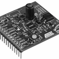
BOARD DEMO LIN SBC FOR ATA6622
Manufacturer
Atmel
Specifications of ATA6622-EK
Main Purpose
Interface, LIN
Embedded
Yes, MCU, 8-Bit
Utilized Ic / Part
ATA6622
Primary Attributes
LIN-SBC (System-Basis-Chip) Transceiver, LIN 2.0, Voltage Regulator, Window Watchdog
Secondary Attributes
4 Power Modes: Pre-Normal, Normal, Sleep, Silent, 20-QFN
Lead Free Status / RoHS Status
Contains lead / RoHS non-compliant


5. Wake-up Scenarios from Silent or Sleep Mode
5.1
5.2
5.3
5.4
12
Remote Wake-up via Dominant Bus State
Local Wake-up via Pin WAKE
Local Wake-up via Pin KL_15
Wake-up Source Recognition
Atmel ATA6622/ATA6624/ATA6626
A voltage less than the LIN Pre_Wake detection V
receiver.
A falling edge at the LIN pin followed by a dominant bus level V
time period (> t
device switches from Silent or Sleep Mode to Fail-safe Mode. The VCC voltage regulator
is/remains activated, the INH pin is switched to high, and the remote wake-up request is indi-
cated by a low level at the RXD pin to generate an interrupt for the microcontroller. A low level
at the LIN pin in the Normal Mode starts the bus wake-up filtering time, and if the IC is
switched to Silent or Sleep Mode, it will receive a wake-up after a positive edge at the LIN pin.
A falling edge at the WAKE pin followed by a low level maintained for a certain time period
(> t
wake-up request is indicated by a low level at the RXD pin to generate an interrupt in the
microcontroller and a strong pull down at TXD. When the Wake pin is low, it is possible to
switch to Silent or Sleep Mode via pin EN. In this case, the wake-up signal has to be switched
to high > 10µs before the negative edge at WAKE starts a new local wake-up request.
A positive edge at pin KL_15 followed by a high voltage level for a certain time period (> t
results in a local wake-up request. The device switches into the Fail-safe Mode. The extra long
wake-up time ensures that no transients at KL_15 create a wake up. The local wake-up
request is indicated by a low level at the RXD pin to generate an interrupt for the microcon-
troller and a strong pull down at TXD. During high-level voltage at pin KL_15, it is possible to
switch to Silent or Sleep Mode via pin EN. In this case, the wake-up signal has to be switched
to low > 250µs before the positive edge at KL_15 starts a new local wake-up request. With
external RC combination, the time is even longer.
The device can distinguish between a local wake-up request (Wake or KL_15 pins) and a
remote wake-up request (dominant LIN bus state). The wake-up source can be read on the
TXD pin in Fail-safe Mode. A high level indicates a remote wake-up request (weak pull up at
the TXD pin); a low level indicates a local wake-up request (strong pull down at the TXD pin).
The wake-up request flag (signalled on the RXD pin), as well as the wake-up source flag (sig-
nalled on the TXD pin), is immediately reset if the microcontroller sets the EN pin to high (see
Figure 4-2 on page 8
wake-up source flag is stored and signalled in Fail-safe Mode at the TXD pin.
WAKE
) results in a local wake-up request. The device switches to Fail-safe Mode. The local
BUS
) and a rising edge at pin LIN result in a remote wake-up request. The
and
Figure 4-3 on page
9) and the IC is in Normal Mode. The last
LINL
at the LIN pin activates the internal LIN
BUSdom
maintained for a certain
4986J–AUTO–03/11
KL_15
)
Related parts for ATA6622-EK
Image
Part Number
Description
Manufacturer
Datasheet
Request
R

Part Number:
Description:
TXRX LIN BUS REG WATCHDOG 20-QFN
Manufacturer:
Atmel
Datasheet:
Part Number:
Description:
TXRX LIN BUS REG WATCHDOG 20-QFN
Manufacturer:
Atmel
Datasheet:

Part Number:
Description:
LIN Bus Transceiver with 3.3V (5V) Regulator and Watchdog
Manufacturer:
ATMEL Corporation
Datasheet:
Part Number:
Description:
(ATA6622 - ATA6626) LIN Bus Transceiver
Manufacturer:
ATMEL Corporation
Datasheet:

Part Number:
Description:
DEV KIT FOR AVR/AVR32
Manufacturer:
Atmel
Datasheet:
Part Number:
Description:
INTERVAL AND WIPE/WASH WIPER CONTROL IC WITH DELAY
Manufacturer:
ATMEL Corporation
Datasheet:
Part Number:
Description:
Low-Voltage Voice-Switched IC for Hands-Free Operation
Manufacturer:
ATMEL Corporation
Datasheet:
Part Number:
Description:
MONOLITHIC INTEGRATED FEATUREPHONE CIRCUIT
Manufacturer:
ATMEL Corporation
Datasheet:
Part Number:
Description:
AM-FM Receiver IC U4255BM-M
Manufacturer:
ATMEL Corporation
Datasheet:
Part Number:
Description:
Monolithic Integrated Feature Phone Circuit
Manufacturer:
ATMEL Corporation
Datasheet:
Part Number:
Description:
Multistandard Video-IF and Quasi Parallel Sound Processing
Manufacturer:
ATMEL Corporation
Datasheet:
Part Number:
Description:
High-performance EE PLD
Manufacturer:
ATMEL Corporation
Datasheet: