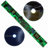
ATAVRFBKIT Atmel, ATAVRFBKIT Datasheet - Page 28

ATAVRFBKIT
Manufacturer Part Number
ATAVRFBKIT
Description
KIT DEMO BALLAST FOR AT90PWM2
Manufacturer
Atmel
Series
AVR®r
Datasheet
1.ATAVRFBKIT.pdf
(35 pages)
Specifications of ATAVRFBKIT
Main Purpose
Lighting, Ballast Control
Embedded
Yes, MCU, 8-Bit
Utilized Ic / Part
AT90PWM2, AT90PWM3
Primary Attributes
18 W, Up to 2 Type T8 Lamps, Dimmable, Auto Detect of Swiss or DALI
Secondary Attributes
Power Factor Corrected (PFC), 90 to 265 VAC, 90 to 370 VDC
Data Bus Width
8 bit
Core Chip
AT90PWM2B
Topology
Boost
No. Of Outputs
1
Dimming Control Type
Digital
Kit Contents
Board CD Docs
Development Tool Type
Hardware / Software - Eval/Demo Board
Rohs Compliant
Yes
Lead Free Status / RoHS Status
Lead free / RoHS Compliant
7.2
ATAVRFBKIT / EVLB001 User Guide
Appendix 2:
Capacitor
Coupled Low
Voltage Supply
-V
+V
PK
PK
AC
AC
C1 charges to Vpk - V
C1 charges to Vpk - V
Small currents for the low voltage supply can be obtained from the AC line at
low loss by means of capacitor coupling as shown in the figures below. To esti-
mate the required size of the coupling capacitor, use the following relationships
for current, charge, voltage and capacitance
1.dQ/dt = I
Figure 7-1. Negative Line Half Cycle
Figure 7-2. Positive Line Half Cycle
1.dV = 2Vpk-Vo-2V
2.dQ = CdV or C = dQ/dV
For example, to obtain 15 mA at 20 VDC from a 220 Vrms 50 Hz line:
1.dQ/dt = (15 millijoules/sec)/(50 cycles/sec) or 0.3 millijoules / cycle.
2.Over 1 cycle, the coupling capacitor (C1) will charge from –220V x 1.4 to
+220V x 1.4 – 20V- V
3. The required C1 ~ 0.3 millijoules/600V or 0.5 uF
- V
+ V
C1
C1
“Negative” line half -cycle:
C1
C1
Ich1
+
-
“Positive” line half -cycle:
DC
Ich2
D
D
D
with polarity shown.
- Vo with polarity shown.
D
. dV = 2*Vpk-Vo-2V
V
V
D
D
V
V
D
D
D
C2
C2
.
.
dV ~= 600V.
Vo
Vo
I
I
DC
DC
7597B–AVR–10/07
Conclusion
7-26


