PS052 Microchip Technology, PS052 Datasheet - Page 2
PS052
Manufacturer Part Number
PS052
Description
BOARD PWR CALIBRATION FOR PS70X
Manufacturer
Microchip Technology
Datasheet
1.PS052.pdf
(12 pages)
Specifications of PS052
Main Purpose
Power Management, Battery Charger
Utilized Ic / Part
PS70x and PS50x
Processor To Be Evaluated
DSPIC30F
Interface Type
RS-232, USB
Lead Free Status / RoHS Status
Request inventory verification / Request inventory verification
Secondary Attributes
-
Embedded
-
Primary Attributes
-
Lead Free Status / Rohs Status
Lead free / RoHS Compliant


PS052
1.0
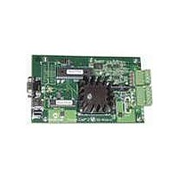
PowerCal 2 is a powerful, easy to use hardware
platform that supports configuration, calibration and
test of Microchip PS7XX and PS5XX ICs. It operates
under the control of Microchip’s development/test
software interfaced to a Windows PC.
The PowerCal 2 board facilitates serial or USB com-
munication between the PC and the SMBus battery
interface. Whether connected to the PC’s serial (RS-232)
or USB port, the PowerCal 2 board must be powered
through an external 12V DC power supply.
2.0
The Microchip PowerCal 2 platform facilitates com-
munication between a battery containing a Microchip
PS5XX or PS7XX IC and a PC running Microchip’s
development/test software. The information that
follows will guide you through the setup of the various
features available.
2.1
• P1 – Serial (RS-232)
• J1 – USB
• J2 – 12V DC power supply
• TBP – Pluggable terminal block for device under
• TBV – Pluggable terminal block for individual cell
DS21817B-page 2
test. Looking into the connector on the board, the
pins from left to right are:
- V+: Battery pack positive
- C: SMBus clock
- D: SMBus data
- T:
- V-: Battery pack negative
voltages. Use depends on the number of series
cells in a Lithium pack. Looking into the connector
on the board, the pins from left to
right are:
- VC4: Top of fourth series cell in pack
- VC3: Top of third series cell in pack
- VC2: Top of second series cell in pack
- VC1: Battery pack positive
T-pin
PRODUCT OVERVIEW
GENERAL SETUP
Connections
2.2
• ADR – Jumper for board address identification
TABLE 2-1:
Legend: O = open, X = connect
2.3
Connect the USB cable from J1 on the PowerCal 2
board to the USB port on the PC. Connect a 12V DC
power supply to J2 and plug it into the electrical outlet.
The board is now powered. Attach your battery to the
TBP connector and launch the Microchip development/
test software on the PC.
2.4
Connect the serial cable from P1 on the PowerCal 2
board to the RS-232 port on the PC. Connect a 12V DC
power supply to J2 and plug it into the electrical outlet.
The board is now powered. Attach your battery to the
TBP connector and launch the Microchip development/
test software on the PC.
2.5
Connections from the individual cell voltages of a
Lithium pack can be attached at TBV to measure and
calibrate the individual cell voltages of the series cells
in the pack. Unused cell voltages should be connected
to V- during VC calibration.
Address
0
1
2
3
4
5
6
7
Jumpers
USB Setup
RS-232 Setup
Individual Cell Voltage Setup
(Optional)
JUMPER POSITION FOR
BOARD ADDRESS ID
3-4
O
O
O
O
X
X
X
X
2004 Microchip Technology Inc.
Jumper Position
2-5
O
O
O
O
X
X
X
X
1-6
O
O
O
O
X
X
X
X
Related parts for PS052
Image
Part Number
Description
Manufacturer
Datasheet
Request
R

Part Number:
Description:
Manufacturer:
Microchip Technology Inc.
Datasheet:
Part Number:
Description:
Manufacturer:
Microchip Technology Inc.
Datasheet:
Part Number:
Description:
Manufacturer:
Microchip Technology Inc.
Datasheet:
Part Number:
Description:
Manufacturer:
Microchip Technology Inc.
Datasheet:
Part Number:
Description:
Manufacturer:
Microchip Technology Inc.
Datasheet:
Part Number:
Description:
Manufacturer:
Microchip Technology Inc.
Datasheet:
Part Number:
Description:
Manufacturer:
Microchip Technology Inc.
Datasheet:
Part Number:
Description:
Manufacturer:
Microchip Technology Inc.
Datasheet: