AD9551/PCBZ Analog Devices Inc, AD9551/PCBZ Datasheet - Page 32
AD9551/PCBZ
Manufacturer Part Number
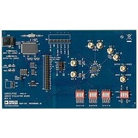
AD9551/PCBZ
Description
BOARD EVAL FOR AD9951
Manufacturer
Analog Devices Inc
Datasheet
1.AD9551PCBZ.pdf
(40 pages)
Specifications of AD9551/PCBZ
Main Purpose
Timing, Clock Generator
Embedded
No
Utilized Ic / Part
AD9551
Primary Attributes
2 Inputs, 2 Outputs, VCO
Secondary Attributes
Graphical User Interface, USB Interface
Silicon Manufacturer
Analog Devices
Application Sub Type
Clock Generator
Kit Application Type
Clock & Timing
Silicon Core Number
AD9551
Kit Contents
Board
Lead Free Status / RoHS Status
Lead free / RoHS Compliant


AD9551
REGISTER MAP DESCRIPTIONS
Control bit functions are active high, and register address values are always hexadecimal, unless otherwise noted.
Serial Port Control (Register 0x00 to Register 0x05)
Table 23.
Address
0x00
0x04
0x05
Output PLL PFD and Charge Pump Control (Register 0x0A to Register 0x0D)
Table 24.
Address
0x0A
0x0B
Bit
7
6
5
4
[3:0]
[7:1]
0
[7:1]
0
Bit
[7:0]
7
6
[5:4]
3
2
1
0
Bit Name
Output PLL PFD and charge
pump current control
Enable SPI control of charge
pump current
Enable SPI control of
antibacklash period
CP mode
Enable CP mode control
PFD feedback input edge control
PFD reference input edge control
Force VCO to midpoint frequency
Bit Name
Unused
LSB first
Soft reset
Unused
Unused
Unused
Readback control
Unused
I/O update
Description
These bits set the magnitude of the output PLL charge pump current. The granularity
is ~3.5 μA with a full-scale magnitude of ~900 μA. Register 0x0A is ineffective unless
Register 0x0B[7] = 1. Default is 0x80, or ~448 μA.
Controls functionality of Register 0x0A.
0 = the device automatically controls the charge pump current (default).
1 = charge pump current defined by Register 0x0A.
Controls functionality of Register 0x0D[7:6].
0 = the device automatically controls the antibacklash period (default).
1 = antibacklash period defined by Register 0x0D[7:6].
Controls the mode of the output PLL charge pump.
00 = tristate.
01 = pump up.
10 = pump down.
11 = normal (default).
Controls functionality Bits[5:4] (CP mode).
0 = the device automatically controls the charge pump mode (default).
1 = charge pump mode is defined by Bits[5:4].
Selects the polarity of the active edge of the output PLL’s feedback input.
0 = positive edge (default).
1 = negative edge.
Selects the polarity of the active edge of the output PLL’s reference input.
0 = positive edge (default).
1 = negative edge.
Selects VCO control voltage functionality.
0 = normal VCO operation (default).
1 = force VCO control voltage to midscale.
Description
Forced to Logic 0 internally, which enables 3-wire mode only.
Bit order for SPI port.
0 = most significant bit and byte first (default).
1 = least significant bit and byte first.
Software initiated reset (register values set to default). This is an autoclearing bit.
Forced to Logic 1 internally, which enables 16-bit mode (the only mode supported by
the device).
Mirrored version of the contents of Register 0x00[7:4] (that is, Bits[3:0] = Bits[7:4]).
Unused.
For buffered registers, serial port readback reads from actual (active) registers instead of
from the buffer.
0 = reads values currently applied to the internal logic of the device (default).
1 = reads buffered values that take effect on next assertion of I/O update.
Unused.
Writing a 1 to this bit transfers the data in the serial I/O buffer registers to the internal
control registers of the device. This is an autoclearing bit.
Rev. B | Page 32 of 40
Related parts for AD9551/PCBZ
Image
Part Number
Description
Manufacturer
Datasheet
Request
R


Part Number:
Description:
±1.7g Dual-Axis IMEMS Accelerometer Evaluation Board
Manufacturer:
Analog Devices Inc
Datasheet:

Part Number:
Description:
Inertial Sensor Evaluation System
Manufacturer:
Analog Devices Inc
Datasheet:
Part Number:
Description:
Manufacturer:
Analog Devices Inc
Datasheet:
Part Number:
Description:
Manufacturer:
Analog Devices Inc
Datasheet:
Part Number:
Description:
Manufacturer:
Analog Devices Inc
Datasheet:
Part Number:
Description:
Manufacturer:
Analog Devices Inc
Datasheet:
Part Number:
Description:
Manufacturer:
Analog Devices Inc
Datasheet:
Part Number:
Description:
Manufacturer:
Analog Devices Inc
Datasheet:
Part Number:
Description:
Manufacturer:
Analog Devices Inc
Datasheet:
Part Number:
Description:
Manufacturer:
Analog Devices Inc
Datasheet:
Part Number:
Description:
Manufacturer:
Analog Devices Inc
Datasheet:
Part Number:
Description:
Manufacturer:
Analog Devices Inc
Datasheet: