SI2400URT-EVB Silicon Laboratories Inc, SI2400URT-EVB Datasheet
SI2400URT-EVB
Specifications of SI2400URT-EVB


Related parts for SI2400URT-EVB

SI2400URT-EVB Summary of contents
Page 1
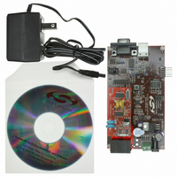
... The Si2400URT- EVB provides an RJ-11 jack and a DB9 connector for interfacing the Si2400URT-EVB to the phone line and data terminal serial port. This allows the Si2400 ISOmodem to operate as a serial modem for straightforward evaluation. To evaluate the Si2400 ISOmodem in an embedded system, the daughter card can be used independently or with the motherboard ...
Page 2
... ATS14=20 Enables +++ escape ATSF4=00 Removes audio mute ATSE4=02 Turns on audio ADC and DAC ATM1 Turns on speaker until carrier negotiated 2. Si2400URT-EVB Setup and Evaluation This section explains how to set up the Si2400URT-EVB for evaluation as an RS-232 or USB interface modem. Jumper settings, power connections, and terminal settings are given ...
Page 3
... Si2400URT-EVB for RS-232 serial operation. Any standard terminal program configured to communicate through a PC COM port can be used to communicate with the Si2400URT-EVB. To connect the modem directly into an embedded system with LVCMOS/TTL levels, install JP8 to disable both the RS-232 and USB interfaces. Connection to the embedded system can be made to JP-3 ...
Page 4
... Also, be sure to disable linefeeds with carriage returns. Connect the RJ-11 jack on the Si2400URT-EVB to an analog phone line or telephone line simulator, such as a Teltone TLS 5. 2.6. Making Connections With the terminal program properly configured and running, apply power to the Si2400URT-EVB. Type “ ...
Page 5
... Si2400DC (daughter card). The versatile power supply allows for a wide range of ac and dc voltages to power the board. RS-232 transceivers and a DB9 connector allow the Si2400URT-EVB to be easily connected other terminal device. Jumper options allow direct access to the LVCMOS/TTL level serial inputs to the Si2400, bypassing the RS-232 transceivers or USB interface ...
Page 6
... Si2400URT-EVB connected to the DTE. Table 3 lists the interface controlled by each motherboard jumper. See Figure 7 on page 13 and Figure 17 on page 23. Jumper JP1 Daughter Card Phone Line Connector. JP2 Daughter Card Digital Connector. JP3 Direct Access Header. JP4 Not Used. JP5 USB Enable (RS-232 Disable). ...
Page 7
... The USB interface is provided by U5. A USB driver for this chip is available for most PC and MAC operating systems on the CD. Figure 3. Jumper Settings for Direct Access Interface Si2400URT-EVB 3.1.8. Direct Access Interface The motherboard supplies power through J3, J4, or USB, power-on reset, and an RJ-11 jack for the modem. ...
Page 8
... PC board capacitance and the tolerance of loading capacitors, must also be taken into account. 3.2.3. Protection /2), The Si2400URT-EVB meets or exceeds all FCC and CC international PTT requirements and recommendations for high-voltage surge and isolation testing without any modification. The protection/isolation circuitry includes C1, C2, C8, C9, FB1, FB2, and RV1. The PCB layout is also a key “ ...
Page 9
... Design The following pages contain the schematics, bill of materials, and layout for the Si2400, including the daughter card and motherboard Rev. 0.7 Si2400URT-EVB 9 ...
Page 10
... Si2400URT-EVB + Rev. 0.7 ...
Page 11
... R27,R28 R31,R32 4.9152 MHz load, 150 ESR, Z1 Z4,Z5 Zener, 5.6 V, 500 mW *Note: Many other suppliers are available. See the Si2400 data sheet. Si2400URT-EVB Value Central Semiconductor Ferrite Bead Fuse HEADER 8x2 4x1 Header_0 NPN, 300 V PNP, 300 V NPN 402 Ω, 1/16 W, ±1% 100 kΩ ...
Page 12
... Si2400URT-EVB EESD_H EECLK_H EECS_H RESET PUSHBUTTON SW 5 Rev. 0.7 ...
Page 13
... Si2400URT-EVB Rev. 0.7 13 ...
Page 14
... Si2400URT-EVB 14 GND Rev. 0.7 ...
Page 15
... VCC 26 Rev. 0.7 Si2400URT-EVB GND 2 15 ...
Page 16
... Si2400URT-EVB C20 R3 AOUT 0 "CTS_U" TP12 TXD_U RXD_U RTS_U CTS_U TXD_T RXD_T RTS_T CTS_T TP15 "CTS_T" DTR_U DSR_U CD_U RI_U DTR_T DSR_T CD_T RI_T 16 VCC C22 0 C21 2 - U10 LM386M-1 820 pF Figure 10. Audio Amplifier Schematic "RXD_U" TP13 1B1 2B1 3B1 4B1 1B2 OE VCC ...
Page 17
... USB_VCC 1.0 uF U11 1 5 USB USB+ GMS05F Figure 12. USB Interface Schematic Si2400URT-EVB U5 8 VBUS 9 RST 7 REGIN 12 SUSPEND 6 VDD C29 C31 + 11 SUSPEND 3 2 GND RI 1 DCD 28 DTR 27 DSR 26 TXD RXD RTS 23 CTS CP2101 Rev. 0.7 R20 TP19 4.7 k RI_U CD_U DTR_U DSR_U ...
Page 18
... Si2400URT-EVB 5. Si24xx Motherboard Bill of Materials Item Quantity Reference 1 5 C1,C3,C12,C15,C29 2 4 C2,C4,C11,C13 C7, C10, C14,C16,C17,C18,C19,C2 0,C22,C23,C31,C32 8 1 C21 9 1 C24 10 4 D1,D2,D3, D6,D7,D8,D9,D10,D11,D1 MMBZ15VDC 2,D13 13 3 FB1,FB2,FB3 Ferrite Bead 14 1 JP1 SOCKET 8X2 15 1 JP2 4X1 Socket 16 1 JP3 HEADER 8X2 17 1 JP4 ...
Page 19
... PCB Layers Si2400URT-EVB Rev. 0.7 19 ...
Page 20
... Si2400URT-EVB 20 Rev. 0.7 ...
Page 21
... Si2400URT-EVB Rev. 0.7 21 ...
Page 22
... Si2400URT-EVB 22 Rev. 0.7 ...
Page 23
... Si2400URT-EVB Rev. 0.7 23 ...
Page 24
... Si2400URT-EVB 24 Rev. 0.7 ...
Page 25
... Si2400URT-EVB Rev. 0.7 25 ...
Page 26
... Si2400URT-EVB 26 Rev. 0.7 ...
Page 27
... Si2400URT-EVB Rev. 0.7 27 ...
Page 28
... Si2400URT-EVB 28 Rev. 0.7 ...
Page 29
... Complete Design Package on CD (See Sales Representative for Details) Silicon Laboratories can provide a complete design package of the Si2400URT-EVB including the following: OrCad Schematics Gerber Files BOM Documentation Contact your local sales representative or Silicon Laboratories headquarter sales for ordering information. Si2400URT-EVB Rev. 0.7 ...
Page 30
... IST Revision 0.6 to Revision 0.7 Updated from Rev 1.0 motherboard to Rev 3.2 motherboard. Updated the following figures and tables: Figures 1,3,5,6,7,8,9,10,11, and 12 Table 6 Added the following figures: Figures 2,19,20,21,22,23,24 Updated "2. Si2400URT-EVB Setup and Evaluation‚" on page 2. 30 Rev. 0.7 ...
Page 31
... N : OTES Si2400URT-EVB Rev. 0.7 31 ...
Page 32
... Si2400URT-EVB C I ONTACT NFORMATION Silicon Laboratories Inc. 4635 Boston Lane Austin, TX 78735 Tel: 1+(512) 416-8500 Fax: 1+(512) 416-9669 Toll Free: 1+(877) 444-3032 Email: SiDAAinfo@silabs.com Internet: www.silabs.com The information in this document is believed to be accurate in all respects at the time of publication but is subject to change without notice. ...