MCP355XDV-MS1 Microchip Technology, MCP355XDV-MS1 Datasheet - Page 24
MCP355XDV-MS1
Manufacturer Part Number
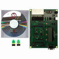
MCP355XDV-MS1
Description
BOARD DEV SENSOR APP MCP355X
Manufacturer
Microchip Technology
Datasheets
1.MCP3553-ESN.pdf
(36 pages)
2.MCP355XDV-MS1.pdf
(36 pages)
3.MCP3551DM-PCTL.pdf
(30 pages)
Specifications of MCP355XDV-MS1
Number Of Adc's
1
Number Of Bits
22
Data Interface
Serial
Inputs Per Adc
1 Differential
Input Range
±0.3 V
Voltage Supply Source
Single Supply
Operating Temperature
-40°C ~ 125°C
Utilized Ic / Part
MCP355x
Processor To Be Evaluated
MCP355x
Interface Type
RS-232, USB
Lead Free Status / RoHS Status
Not applicable / Not applicable
Lead Free Status / RoHS Status
Lead free / RoHS Compliant, Not applicable / Not applicable
Available stocks
Company
Part Number
Manufacturer
Quantity
Price
Company:

Part Number:
MCP355XDV-MS1
Manufacturer:
MICROCHIP
Quantity:
12 000


MCP3550/1/3
5.4.1
The device enters Continuous Conversion mode if no
rising edge of CS is seen during t
consecutive conversions ensue. SDO/RDY will be
high, indicating that a conversion is in process. When
a conversion is complete, SDO/RDY will change to a
Low state. With the Low state of SDO/RDY after this
first conversion, the conversion data can be accessed
with the combination of SCK and SDO/RDY. If the data
ready event happens during the clocking out of the
data, the data ready bit will be displayed after the
complete 24-bit word communication (i.e., the data
ready event will not interrupt a data transfer).
If 24 bits of data are required from this conversion, they
must be accessed during this communication. You can
terminate data transition by bringing CS high, but the
remaining data will be lost and the converter will go into
Shutdown mode. Once the data has been transmitted
by the converter, the SDO/RDY pin will remain in the
LSB state until the 25th falling edge of SCK. At this
point, SDO/RDY is released from the Data Acquisition
mode and changed to the RDY state.
DS21950E-page 24
Note:
READY FUNCTION OF SDO/RDY
PIN IN CONTINUOUS CONVERSION
MODE
The RDY state is not latched to CS in this
mode; the RDY flag dynamically updates
on the SDO/RDY pin and remains in this
state until data is clocked out using the
SCK pin.
CONV
and
5.4.2
It is possible to use only two wires to communicate with
the MCP3550/1/3 devices. In this state, the device is
always in Continuous Conversion mode, with internal
conversions continuously occurring. This mode can be
entered by having CS low during power-up or changing
it to a low position after power-up. If CS is low at power-
up, the first conversion of the converter is initiated
approximately 300 µs after the power supply has
stabilized.
2-WIRE CONTINUOUS
CONVERSION OPERATION,
(CS TIED PERMANENTLY LOW)
© 2009 Microchip Technology Inc.
Related parts for MCP355XDV-MS1
Image
Part Number
Description
Manufacturer
Datasheet
Request
R

Part Number:
Description:
Manufacturer:
Microchip Technology Inc.
Datasheet:
Part Number:
Description:
Manufacturer:
Microchip Technology Inc.
Datasheet:
Part Number:
Description:
Manufacturer:
Microchip Technology Inc.
Datasheet:
Part Number:
Description:
Manufacturer:
Microchip Technology Inc.
Datasheet:
Part Number:
Description:
Manufacturer:
Microchip Technology Inc.
Datasheet:
Part Number:
Description:
Manufacturer:
Microchip Technology Inc.
Datasheet:
Part Number:
Description:
Manufacturer:
Microchip Technology Inc.
Datasheet:
Part Number:
Description:
Manufacturer:
Microchip Technology Inc.
Datasheet: