AD9204-20EBZ Analog Devices Inc, AD9204-20EBZ Datasheet - Page 24
AD9204-20EBZ
Manufacturer Part Number
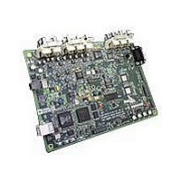
AD9204-20EBZ
Description
BOARD EVALUATION 20MSPS AD9204
Manufacturer
Analog Devices Inc
Datasheet
1.AD9204BCPZ-20.pdf
(36 pages)
Specifications of AD9204-20EBZ
Number Of Adc's
2
Number Of Bits
10
Sampling Rate (per Second)
20M
Data Interface
Serial, SPI™
Inputs Per Adc
1 Differential
Input Range
1 ~ 2 Vpp
Power (typ) @ Conditions
*
Voltage Supply Source
Single Supply
Operating Temperature
-40°C ~ 85°C
Utilized Ic / Part
AD9204
Silicon Manufacturer
Analog Devices
Application Sub Type
ADC
Kit Application Type
Data Converter
Silicon Core Number
AD9204
Tool / Board Applications
General Purpose MCU, MPU, DSP, DSC
Development Tool Type
Hardware / Software - Starter Kit
Lead Free Status / RoHS Status
Lead free / RoHS Compliant


AD9204
If a low jitter clock source is not available, another option is to
ac couple a differential PECL signal to the sample clock input
pins, as shown in Figure 52. The
AD9513/AD9514/AD9515/AD9516/AD9517
excellent jitter performance.
A third option is to ac couple a differential LVDS signal to the
sample clock input pins, as shown in Figure 53. The AD9510/
AD9511/AD9512/AD9513/AD9514/AD9515/AD9516/AD9517
clock drivers offer excellent jitter performance.
In some applications, it may be acceptable to drive the sample
clock inputs with a single-ended 1.8 V CMOS signal. In such
applications, drive the CLK+ pin directly from a CMOS gate, and
bypass the CLK− pin to ground with a 0.1 μF capacitor (see
Figure 54).
CLOCK
CLOCK
CLOCK
CLOCK
CLOCK
INPUT
INPUT
INPUT
INPUT
INPUT
Figure 54. Single-Ended 1.8 V CMOS Input Clock (Up to 200 MHz)
50kΩ
50kΩ
Figure 53. Differential LVDS Sample Clock (Up to 625 MHz)
Figure 52. Differential PECL Sample Clock (Up to 625 MHz)
50Ω
1
50Ω RESISTOR IS OPTIONAL.
0.1µF
1
0.1µF
0.1µF
0.1µF
0.1µF
50kΩ
50kΩ
V
CC
1kΩ
1kΩ
LVDS DRIVER
PECL DRIVER
CMOS DRIVER
AD951x
AD951x
AD951x
240Ω
AD9510/AD9511/AD9512/
OPTIONAL
240Ω
100Ω
0.1µF
100Ω
100Ω
0.1µF
0.1µF
0.1µF
0.1µF
clock drivers offer
0.1µF
CLK+
CLK–
CLK+
CLK–
CLK+
CLK–
ADC
ADC
ADC
Rev. 0 | Page 24 of 36
Input Clock Divider
The AD9204 contains an input clock divider with the ability
to divide the input clock by integer values between 1 and 8.
Optimum performance can be obtained by enabling the
internal duty cycle stabilizer (DCS) when using divide ratios
other than 1, 2, or 4.
The AD9204 clock divider can be synchronized using the
external SYNC input. Bit 1 and Bit 2 of Register 0x100 allow
the clock divider to be resynchronized on every SYNC signal
or only on the first SYNC signal after the register is written. A
valid SYNC causes the clock divider to reset to its initial state.
This synchronization feature allows multiple parts to have their
clock dividers aligned to guarantee simultaneous input
sampling.
Clock Duty Cycle
Typical high speed ADCs use both clock edges to generate
a variety of internal timing signals and, as a result, may be
sensitive to clock duty cycle. Commonly, a ±5% tolerance is
required on the clock duty cycle to maintain dynamic
performance characteristics.
The AD9204 contains a duty cycle stabilizer (DCS) that retimes
the nonsampling (falling) edge, providing an internal clock
signal with a nominal 50% duty cycle. This allows the user to
provide a wide range of clock input duty cycles without affecting
the performance of the AD9204. Noise and distortion perform-
ance are nearly flat for a wide range of duty cycles with the DCS
on, as shown in Figure 55.
Jitter in the rising edge of the input is still of concern and is not
easily reduced by the internal stabilization circuit. The duty
cycle control loop does not function for clock rates less than
20 MHz nominally. The loop has a time constant associated
with it that must be considered in applications in which the
clock rate can change dynamically. A wait time of 1.5 μs to 5 μs
is required after a dynamic clock frequency increase or decrease
before the DCS loop is relocked to the input signal.
80
75
70
65
60
55
50
45
40
10
20
Figure 55. SNR vs. DCS On/Off
30
DCS ON
POSITIVE DUTY CYCLE (%)
DCS OFF
40
50
60
70
80
Related parts for AD9204-20EBZ
Image
Part Number
Description
Manufacturer
Datasheet
Request
R

Part Number:
Description:
10 Bit 40 Msps Dual Low Power ADC
Manufacturer:
Analog Devices Inc
Datasheet:
Part Number:
Description:
10 Bit 65 Msps Dual Low Power ADC
Manufacturer:
Analog Devices Inc
Datasheet:
Part Number:
Description:
10 Bit 80 Msps Dual Low Power ADC
Manufacturer:
Analog Devices Inc
Datasheet:

Part Number:
Description:
±1.7g Dual-Axis IMEMS Accelerometer Evaluation Board
Manufacturer:
Analog Devices Inc
Datasheet:
Part Number:
Description:
Inertial Sensor Evaluation System
Manufacturer:
Analog Devices Inc
Datasheet:
Part Number:
Description:
Manufacturer:
Analog Devices Inc
Datasheet:
Part Number:
Description:
Manufacturer:
Analog Devices Inc
Datasheet:
Part Number:
Description:
Manufacturer:
Analog Devices Inc
Datasheet:
Part Number:
Description:
Manufacturer:
Analog Devices Inc
Datasheet:
Part Number:
Description:
Manufacturer:
Analog Devices Inc
Datasheet:
Part Number:
Description:
Manufacturer:
Analog Devices Inc
Datasheet:
Part Number:
Description:
Manufacturer:
Analog Devices Inc
Datasheet:
Part Number:
Description:
Manufacturer:
Analog Devices Inc
Datasheet: