STEVAL-CCA007V1 STMicroelectronics, STEVAL-CCA007V1 Datasheet - Page 23
STEVAL-CCA007V1
Manufacturer Part Number
STEVAL-CCA007V1
Description
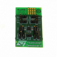
BOARD EVAL BASED ON TS2012IQT
Manufacturer
STMicroelectronics
Specifications of STEVAL-CCA007V1
Design Resources
STEVAL-CCA007V1 Gerber Files STEVAL-CCA007V1 Schematic STEVAL-CCA007V1 Bill of Material
Amplifier Type
Class D
Output Type
2-Channel (Stereo)
Max Output Power X Channels @ Load
2.8W x 2 @ 4 Ohm
Voltage - Supply
2.5 V ~ 5.5 V
Operating Temperature
-40°C ~ 85°C
Board Type
Fully Populated
Utilized Ic / Part
TS2012
Description/function
Audio Amplifiers
Operating Supply Voltage
2.5 V to 5.5 V
Output Power
2.2 W
Product
Audio Modules
Lead Free Status / RoHS Status
Lead free / RoHS Compliant
For Use With/related Products
TS2012
Other names
497-8258


TS2012
4.4
4.5
Low frequency response
If a low frequency bandwidth limitation is required, it is possible to use input coupling
capacitors. In the low frequency region, the input coupling capacitor C
effect. C
off frequency (see
So, for a desired cut-off frequency F
with F
The input impedance Z
is also a tolerance around the typical value (see
the tolerance of the F
●
●
Decoupling of the circuit
Power supply capacitors, referred to as C
TS2012.
The TS2012 has a typical switching frequency of 280kHz and output fall and rise time about
5ns. Due to these very fast transients, careful decoupling is mandatory.
A 1µF ceramic capacitor between each PVCC and PGND and also between AVCC and
AGND is enough, but they must be located very close to the TS2012 in order to avoid any
extra parasitic inductance created by a long track wire. Parasitic loop inductance, in relation
with di/dt, introduces overvoltage that decreases the global efficiency of the device and may
cause, if this parasitic inductance is too high, a TS2012 breakdown.
In addition, even if a ceramic capacitor has an adequate high frequency ESR value, its
current capability is also important. A 0603 size is a good compromise, particularly when a
4Ω load is used.
Another important parameter is the rated voltage of the capacitor. A 1µF/6.3V capacitor
used at 5V, loses about 50% of its value. With a power supply voltage of 5V, the decoupling
value, instead of 1µF, could be reduced to 0.5µF. As C
THD+N in the medium to high frequency region, this capacitor variation becomes decisive.
In addition, less decoupling means higher overshoots which can be problematic if they reach
the power supply AMR value (6V).
F
F
CLmax
CLmin
CL
in
in Hz, Z
forms, with the input impedance Z
=
=
0.915
1.103
in
Table 5
in Ω and C
⋅
⋅
CL
F
F
in
CL
CL
:
is for the whole power supply voltage range, typically 30kΩ . There
to
Table
in
in F.
F
C
7):
CL
CL
in
=
C
=
in
--------------------------------------------- -
2
S
------------------------------------------- -
2
is calculated as follows:
⋅
,C
⋅
in
π
SL
π
, a first order high-pass filter with a -3dB cut-
⋅
⋅
,C
Z
1
1
Table 5
Z
in
SR
in
⋅
⋅
are needed to correctly bypass the
F
C
S
CL
in
has particular influence on the
to
Table
7). You can also calculate
Application information
in
starts to have an
23/30
Related parts for STEVAL-CCA007V1
Image
Part Number
Description
Manufacturer
Datasheet
Request
R

Part Number:
Description:
EVAL BOARD CC DRVR HI DENSE LEDS
Manufacturer:
STMicroelectronics
Datasheet:

Part Number:
Description:
EVAL BOARD CC DRVR HI DENSE LEDS
Manufacturer:
STMicroelectronics
Datasheet:

Part Number:
Description:
BATTERY CHARGER CELL PHONE
Manufacturer:
STMicroelectronics
Datasheet:

Part Number:
Description:
BOARD EVAL FOR MEMS SENSORS
Manufacturer:
STMicroelectronics
Datasheet:

Part Number:
Description:
KIT DEV STARTER ST10F276Z5
Manufacturer:
STMicroelectronics
Datasheet:

Part Number:
Description:
BOARD EVAL UPS 450W VOUT=220V
Manufacturer:
STMicroelectronics
Datasheet:

Part Number:
Description:
BOARD STLM75/STDS75/ST72F651
Manufacturer:
STMicroelectronics
Datasheet:

Part Number:
Description:
EVAL BOARD ENERGY METER MONO
Manufacturer:
STMicroelectronics
Datasheet:

Part Number:
Description:
EVAL BOARD ENERGY METER MONO
Manufacturer:
STMicroelectronics
Datasheet:

Part Number:
Description:
EVAL BOARD ENERGY METER MONO
Manufacturer:
STMicroelectronics
Datasheet:

Part Number:
Description:
STMicroelectronics [RIPPLE-CARRY BINARY COUNTER/DIVIDERS]
Manufacturer:
STMicroelectronics
Datasheet:
Part Number:
Description:
STMicroelectronics [LIQUID-CRYSTAL DISPLAY DRIVERS]
Manufacturer:
STMicroelectronics
Datasheet:
Part Number:
Description:
BOARD EVAL FOR MEMS SENSORS
Manufacturer:
STMicroelectronics
Datasheet: