DM300023 Microchip Technology, DM300023 Datasheet - Page 21
DM300023
Manufacturer Part Number
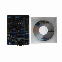
DM300023
Description
KIT DEMO DSPICDEM SMPS BUCK
Manufacturer
Microchip Technology
Series
dsPIC™r
Datasheets
1.AC164335.pdf
(286 pages)
2.DM300023.pdf
(22 pages)
3.DM300023.pdf
(18 pages)
4.DM300023.pdf
(50 pages)
5.DM300023.pdf
(16 pages)
Specifications of DM300023
Main Purpose
DC/DC, Step Down
Outputs And Type
2, Non-Isolated
Voltage - Input
7 ~ 15V
Regulator Topology
Buck
Board Type
Fully Populated
Utilized Ic / Part
dsPIC30F2020
Processor To Be Evaluated
dsPIC30F202x/1010
Interface Type
RS-232
Lead Free Status / RoHS Status
Lead free / RoHS Compliant
Current - Output
-
Voltage - Output
-
Power - Output
-
Frequency - Switching
-
Lead Free Status / Rohs Status
Lead free / RoHS Compliant
Available stocks
Company
Part Number
Manufacturer
Quantity
Price
Company:

Part Number:
DM300023
Manufacturer:
Microchip Technology
Quantity:
135
Company:
Part Number:
DM300023
Manufacturer:
MICROCHIP
Quantity:
12 000


2.3
© 2006 Microchip Technology Inc.
PROGRAM OR DEBUG SELECTION SWITCH (SW2)
The dsPIC30F2020 device program pins (PGC/PGD) are multiplexed with the UART
pins (U1RX and U1TX). A DIP switch (SW2) selects whether the default programming
pin pair (PGC/PGC) are used to program the device. Because PGC and PGD are
multiplexed with the UART pins, the pins can only be used to program the device.
Debugging is not possible with PGC/EMUC and PGD/EMUD.
When SW2 is in the PGM position, the PGC/PGD and PGC1/PGD1 pins are connected
to the ICD 2. This configuration allows you to program the device with either the default
programming pin pair (PGC/PGD) or the first set of auxiliary programming pins
(PGC1/PGD1). Emulation and debugging in not possible when SW2 is in the PGM
position and the default programming/emulation pins are selected (via the
Configuration bits).
When SW2 is in the DEBUG position, PGC1/EMUC1 and PGD1/EMUD1 must be
selected as the debugging pin pair in the Configuration bit settings window. Both
programming and debugging are possible in this configuration.
DS70181A-page 17
Related parts for DM300023
Image
Part Number
Description
Manufacturer
Datasheet
Request
R

Part Number:
Description:
Manufacturer:
Microchip Technology Inc.
Datasheet:
Part Number:
Description:
Manufacturer:
Microchip Technology Inc.
Datasheet:
Part Number:
Description:
Manufacturer:
Microchip Technology Inc.
Datasheet:
Part Number:
Description:
Manufacturer:
Microchip Technology Inc.
Datasheet:
Part Number:
Description:
Manufacturer:
Microchip Technology Inc.
Datasheet:
Part Number:
Description:
Manufacturer:
Microchip Technology Inc.
Datasheet:
Part Number:
Description:
Manufacturer:
Microchip Technology Inc.
Datasheet:
Part Number:
Description:
Manufacturer:
Microchip Technology Inc.
Datasheet: